Facebook
 Google
 GitHub
 Linkedin
I have an old 6ft fluorescent lamp that works for a few minutes but then suddenly makes a loud noise whereupon I quickly switch it off.
I suspect a component in the ballast is overheating.
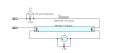
The ballast uses an 8.4uF capacitor in series with a 500mH choke (i.e. lead-lag power factor compensation).
The capacitor indicates it has a built in internal resistor. I measure about 2K using a DMM.
I have a few questions:-
Is the internal resistor there purely to act as a bleed resistor to discharge the capacitor after power is removed?
Does an internal resistance of 2K seem sensible? It seems low to me. Surely it will waste power and get hot?
How do you calculate the power disspation in the 2K resistor bearing in mind the tube is non-linear device?
I am thinking of replacing the capacitor with one of similar value but without the internal resistor.
I suspect a component in the ballast is overheating.
The ballast uses an 8.4uF capacitor in series with a 500mH choke (i.e. lead-lag power factor compensation).
The capacitor indicates it has a built in internal resistor. I measure about 2K using a DMM.
I have a few questions:-
Is the internal resistor there purely to act as a bleed resistor to discharge the capacitor after power is removed?
Does an internal resistance of 2K seem sensible? It seems low to me. Surely it will waste power and get hot?
How do you calculate the power disspation in the 2K resistor bearing in mind the tube is non-linear device?
I am thinking of replacing the capacitor with one of similar value but without the internal resistor.
Attachments
-
 30.5 KB Views: 10
Last edited:
")