Consider this. I have a 12V battery with two parallel resistors connected to it. One resistor is dissipating 12W, what is the size of the other resistor?
Consider this. I have a 12V battery with two parallel resistors connected to it. One resistor is dissipating 12W, what is the size of the other resistor?
To be completely honest I do not possess virtually any knowledge of electronics.
I am very interested to see the final solution of this problem with or without the solution procedure.
Thank you.
Okay, how about this one: My car gets 30mpg and I live 60 miles from where I work. How big is my gas tank?
If you have no knowledge of electronics, then what is the point of even looking at a problem like this? Whether it has a solution or not, you would lack the knowledge to know how to find it or to understand what the solution might mean once it was found.
What is the point of this problem -- meaning, what is the context of why you are trying to work it? That might help us figure out what the best way is to help you toward that goal.
What is the point of this problem -- meaning, what is the context of why you are trying to work it? That might help us figure out what the best way is to help you toward that goal.
It is some kind of bet. And as I do not have the necessary knowledge of electronics I'd like to hear what the experts think about this. Of course I would love to see finally solution to the problem if it exists. And if this problem is not solvable I like to hear that too, without analogy if posible.
PS
Oh now I remember, the problem supposedly has many possible solutions. Any solutions is valid.
If we assume that the components are ideal -- and we pretty much have to make the assumption -- then you can pick the inductor and capacitor values at random and be all but guaranteed that you have a "solution". I'm not sure that you could even find a set of values that would not be a "solution".
Anyway, every coil has a resistance, every wire has too.Every capacitor has a resistance and inductance part too. Every wire has inductance (although negligible in this case.
The true resistance for such a big inductor is much more than 0.1R.
Not with Multisim (the simulation I used).
Anyway, every coil has a resistance, every wire has too.Every capacitor has a resistance and inductance part too. Every wire has inductance (although negligible in this case.
The true resistance for such a big inductor is much more than 0.1R.
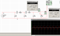
I played with the online Sim tools and looks that changing the value of L1 elements can fine-tune the voltage at the resistor R1. Is there an equation that describes how the value of L1 elements affect the value of the voltage at the resistor R1?
I still don't see the goal. Okay, it's a bet of some kind. Fine. But what constitutes a solution? You have two ideal voltage sources, which mean that they will drive the nodes they are connected to at their terminal voltages no matter how much current they have to supply in order to do it. Be it 0A, 10A, a trillion amps, or infinity. You have a lamp with a fixed DC voltage across it that is dissipating 100W, so it has whatever resistance is needed to dissipate 100W with that voltage across it. The right hand capacitor is clamped to the DC voltage of the right hand source, so it has some charge that is fixed and unchanging. So the only thing that could cause a problem would be for the rest of the components to result in a short, at the frequency of the AC source, between the terminals of the two sources.
I played with the online Sim tools and looks that changing the value of L1 elements can fine-tune the voltage at the resistor R1. Is there an equation that describes how the value of L1 elements affect the value of the voltage at the resistor R1?
Fine tune it TO WHAT??? "Fine tuning" something implies that it isn't quite what you want and so you tweak something to get it closer to what you want. What do you want the voltage at resistor R1 to BE?
This is how I understood the problem.
I have one AC source at the left. With three capacitors and two coils I must raise the initial AC voltage to 230 volts that 100 watt incandescent light bulb will light at full power. At the right side is voltmeter with reading not a DC source.
This is how I understood the problem.
I have one AC source at the left. With three capacitors and two coils I must raise the initial AC voltage to 230 volts that 100 watt incandescent light bulb will light at full power. At the right side is voltmeter with reading not a DC source.
 Facebook
 Google
 GitHub
 Linkedin