Impedance Measurement

Thread Starter

harvester

Joined Mar 12, 2014
6
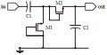
What is the input and output impedance of the circuit?
Attempt of solution:
I can represent the transistors as their effective "on" resistance Ron so the input and output impedance can be derived by simple series and parallel connections of resistors and capacitors.
​
The problem is the transistors are not on at the same time.
​
Will I be getting 2 input and output impedance since there will be two phases?
Is there a way to find a single valued input impedance since I will be matching that value to an antenna?
 

Attachments

blah2222

Joined May 3, 2010
582
What is the input and output impedance of the circuit?
Attempt of solution:
I can represent the transistors as their effective "on" resistance Ron so the input and output impedance can be derived by simple series and parallel connections of resistors and capacitors.
​
The problem is the transistors are not on at the same time.
​
Will I be getting 2 input and output impedance since there will be two phases?
Is there a way to find a single valued input impedance since I will be matching that value to an antenna?
Work out the impedance values for both states and see if they differ.
 

Thread Starter

harvester

Joined Mar 12, 2014
6
Thanks for the reply. The two impedance values are different. How do we go on about using these two values for maximum power transfer from a source of one valued impedance?
 

BytetoEat

Joined Mar 5, 2014
25
although in typical Nfets these would be off, its totally possible to fabricate them so they are both on at the same time with Vt being set to the correct value. However, I dont know if anyone would use this.

As for your question, output and input impedance are based on certain formula's which you should have learned in your class. The ac small signal resistance looking into a diode connected fet is 1/gm, and you only care about the state of teh circuit when its transferring energy to the output. When your input goes negative, the left most fet conducts and doesnt allow the node to go below -Vthreshold. In this state no power is transferred to your output, so ignore it. On the other state, this is the one that matters because its where youre transferring the input signal to your output.
 
Top