Facebook
 Google
 GitHub
 Linkedin
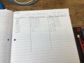
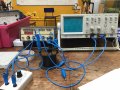
I have an a.c sig gen with an inductor, resistor in series and an o.c.r in parallel. I have measured frequency and voltage across the coil. How do I find the reactance and inductance of the coil without using the equation L=(m x N^2x pi x r^2)/l ??
I know XL=2pifL and for an RL circuit (current through L)=VL/(root R^2+XL^2).
im stuck as to how to get there, it’d be amazing if you could help me
thank you very much!
I know XL=2pifL and for an RL circuit (current through L)=VL/(root R^2+XL^2).
im stuck as to how to get there, it’d be amazing if you could help me
thank you very much!