 Facebook
 Google
 GitHub
 Linkedin
Hey everyone! I am working on a project where I want to get a TFT to display signals from my ESP32. Before I get there, I need to understand why I cannot get even an example code to show on the TFT. So everything has been trial and error thus far. I am hoping someone can review my trials and help me figure out what I am missing. Some things I have learned along the way...
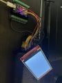
1) Device: 3.5" SPI TFT Module ILI9488 Driver, SPI Bus, 320x480, non touch (SKU: MSP3521)
2) There are predefined pins for the TFT that cannot be changed based on the TFT_eSPI library by Bodmer: DC_2, CS_15, MOSI_23, SCLK_18, BL_-1 (I have been running this to 3.3V for always high), and RST_ -1 (not sure exactly what to do with this but from what I have read I do not need to wire this).
https://forum.arduino.cc/t/power-save-9486-tft-with-esp32/701118
3) When using ESP32 I have read that the J1 channel needs to be soldered together since the ESP32 has the 3.3V output...? I did this but can always reverse it. Shouldn't affect the outcome. But that did not help. I also went through all of the files and defined the correct driver (ILI9488), defined the correct pins, included the correct setup (setup 21 ESP32 and ILI9488 SPI BUS)
3) When I run an example code, I get a blank white screen. Somewhere along the line I am missing something..
If anyone has any experience working with these TFTs and could drop some guidance along the way based on something I have not covered or anything really would be of much help. Thank you!
")


