 Facebook
 Google
 GitHub
 Linkedin
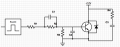
this is my basic design for switching performance for IGBT Sic. as attach.
from what i understand, IGBT turn on and turn off are controlled gate voltage.
base on the circuit design that i did:
I hope to get some advice on my design...
from what i understand, IGBT turn on and turn off are controlled gate voltage.
base on the circuit design that i did:
- once it off, the gate current Ig flow until the input gate capacitance Ciee of the IGBT.
- turn on and turn off is decided by the values of ( R1,R2,R3,C1,C2)
- smaller value of resistance (R1,R2) results in a shorter charging time.
- (C1,R1) can speed up the turn on power.
- when the Vg is disconnected and the gate capacitance discharge into R3.
I hope to get some advice on my design...
Attachments
-
 88.1 KB Views: 59


