Identifying whether the getter compound in a valve tube is consumed?

Thread Starter

Rahulk70

Joined Dec 16, 2016
538
Hi,

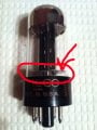
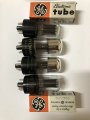
I recently got four 6X5 Rectifier tubes on eBay for like $5 as spares for replacement for the rectifier in my Eico 950B tester.
But on checking the newly received tubes I noticed that two of the tubes don't have the silvery getter compound in them.

Is this normal? The seller had put the tubes on a Hickok 539C tester and they all are strong.

Thanks in advance.
 

Attachments

recklessrog

Joined May 23, 2013
985
The "gettering" in a vacuum tube is not really consumed in normal use, it is there to absorb residual gasses after air is pumped out during manufacture. Once the air is pumped out, the getter ring, usually visible close to the silvering, is "fired" and deposits the getter onto the inside of the tube glass envelope. If air enters the glass due to cracks etc, the getter will turn white, and the tube will then become "soft" ie. contains gasses not meant to be there and will impair/destroy the Tubes/valves performance.
Different manufacturers may put the getter ring in different places.Sometimes on the sides and not the top. I have noticed some very cheap Chinese tubes/Valves do not appear to have any gettering, probably to save costs, and rely only on the initial vacuum process.
 
Last edited:

recklessrog

Joined May 23, 2013
985
To avoid confusion, the term "gettering" refers to the actual silver coating inside the glass. The getter ring (two separate words) is a metal ring mounted inside, which has a channel containing a compound that when heated by an induction heater, "fires" the compound causing it to be deposited onto the glass.
 

spinnaker

Joined Oct 29, 2009
7,830
To avoid confusion, the term "gettering" refers to the actual silver coating inside the glass. The getter ring (two separate words) is a metal ring mounted inside, which has a channel containing a compound that when heated by an induction heater, "fires" the compound causing it to be deposited onto the glass.

How do you know all of this? :) Were you involved with manufacture of vacuum tubes back in the day?
 

recklessrog

Joined May 23, 2013
985
How do you know all of this? :) Were you involved with manufacture of vacuum tubes back in the day?
Although I worked at Hivac valves for a short while in the sixties, I actually knew it long before that. Guess I was a nerdy kid and read up on anything and everything on electronics from a very early age. My dad had been in Radar during the war and was an Radio "Ham," he taught me the resistor colour codes when I was around 4 or 5 :) (to this day I can look at a jumble of a hundred mixed value resistors and pick out a wanted one in a jiffy)
I made a TRF radio from a design in "Practical Wireless" that used ex WD acorn valves and ex RAF headphones. I took it to my infant school and all the other kids and the masters played with it. Trouble was, they ran the batteries flat :(
Just went on from there!.
 
Last edited:

Thread Starter

Rahulk70

Joined Dec 16, 2016
538
The "gettering" in a vacuum tube is not really consumed in normal use, it is there to absorb residual gasses after air is pumped out during manufacture. Once the air is pumped out, the getter ring, usually visible close to the silvering, is "fired" and deposits the getter onto the inside of the tube glass envelope. If air enters the glass due to cracks etc, the getter will turn white, and the tube will then become "soft" ie. contains gasses not meant to be there and will impair/destroy the Tubes/valves performance.
Different manufacturers may put the getter ring in different places.Sometimes on the sides and not the top. I have noticed some very cheap Chinese tubes/Valves do not appear to have any gettering, probably to save costs, and rely only on the initial vacuum process.
Hi,

Thanks for the info.I do know that it does turn chalky when gases start leaking into the tube. These are used but since they were tested strong I didn't suspect them to be faulty. But I could be wrong. Well one of the clear tube's has it's marking wiped off and the other is Raytheon. So, at least one is not Chinese or cheap quality. As you are experienced can you tell me what symptopms I can expect if the tube is out of getter. I could try putting it on my Eico 950B and test it? But a little scared:rolleyes:
 

recklessrog

Joined May 23, 2013
985
Hi,

Thanks for the info.I do know that it does turn chalky when gases start leaking into the tube. These are used but since they were tested strong I didn't suspect them to be faulty. But I could be wrong. Well one of the clear tube's has it's marking wiped off and the other is Raytheon. So, at least one is not Chinese or cheap quality. As you are experienced can you tell me what symptopms I can expect if the tube is out of getter. I could try putting it on my Eico 950B and test it? But a little scared:rolleyes:
Well we have a saying in servicing, "If in doubt, chuck it out" If the tube is gassed, there is a possibility of arc over between the electrodes due to air not having the same insulating properties as a vacuum. A proper valve/tube tester would be the best way to be sure. As you have some that obviously have the gettering intact, use them and forget the others.
 

Thread Starter

Rahulk70

Joined Dec 16, 2016
538
Well we have a saying in servicing, "If in doubt, chuck it out" If the tube is gassed, there is a possibility of arc over between the electrodes due to air not having the same insulating properties as a vacuum. A proper valve/tube tester would be the best way to be sure. As you have some that obviously have the gettering intact, use them and forget the others.
Okay, I'll use the ones that have the getter first and only use the other two if I'm completely out of options.
I'm yet to receive my tube tester from ebay. But I'll post a link of the tube I purchased from.

https://www.ebay.com/itm/LOT-OF-4-6...a0qdATR73A%3D&orig_cvip=true&nordt=true&rt=nc
 

MisterBill2

Joined Jan 23, 2018
27,197
You could also replace the rectifier tubes with 1N4005 diodes soldered across the tube socket below. Then never need to replace rectifier tubes aain, and also no need to be concerned about heater to cathode short circuits. And it wold cost less than a dollar for the two diodes.
 

Thread Starter

Rahulk70

Joined Dec 16, 2016
538
You could also replace the rectifier tubes with 1N4005 diodes soldered across the tube socket below. Then never need to replace rectifier tubes aain, and also no need to be concerned about heater to cathode short circuits. And it wold cost less than a dollar for the two diodes.
I did first thing of using the selenium rectifiers I had or even the diodes you had mentioned. But what made me think is that wouldn't there be a voltage spike on the eye tube which in case of the rectifier tube would gradually raise the voltage till the eye tube glows completely.
 

MisterBill2

Joined Jan 23, 2018
27,197
I did first thing of using the selenium rectifiers I had or even the diodes you had mentioned. But what made me think is that wouldn't there be a voltage spike on the eye tube which in case of the rectifier tube would gradually raise the voltage till the eye tube glows completely.
This is the first mention of an eye tube, and so it is a bit of a puzzle. What is true is that the B+ voltage will come on immediately, before the tubes heat up and start drawing current, and so it will rise up to a higher value than when everything is fully warmed and drawing current. It is also true that the B+ will be a bit higher. That means that any eye tube will be a bit brighter. But the glow pattern is controlled by the grid voltage and so that portion of the function should be unchanged. ALSO, it would work quite well, once the diodes are installed, to leave the 6X5 out of it's socket, since the rectifier function is done by the diodes now. The only potential problem would be if the B+ was now higher than the rated voltage of the filter capacitors.
 

bertus

Joined Apr 5, 2008
22,887
Hello,

To avoid the spike using silicon diodes, you could put a low value NTC in series with the diode.
The NTC will reduce the intitial peak.

Bertus
 

MisterBill2

Joined Jan 23, 2018
27,197
Hello,

To avoid the spike using silicon diodes, you could put a low value NTC in series with the diode.
The NTC will reduce the intitial peak.

Bertus
It is a voltage peak, not a current spike. AND it peaks because there is nothing drawing any current initially. It would cut down the current spike that happens as the capacitors charge, but that is not the concern, I don't think, since the transformer limits the current for that very brief time period..
 

bertus

Joined Apr 5, 2008
22,887
Hello,
It is a voltage peak, not a current spike. AND it peaks because there is nothing drawing any current initially. It would cut down the current spike that happens as the capacitors charge, but that is not the concern, I don't think, since the transformer limits the current for that very brief time period..
Agreed, the final resistance of the NTC will lower the voltage a bit.

Bertus
 

Thread Starter

Rahulk70

Joined Dec 16, 2016
538
This is the first mention of an eye tube, and so it is a bit of a puzzle. What is true is that the B+ voltage will come on immediately, before the tubes heat up and start drawing current, and so it will rise up to a higher value than when everything is fully warmed and drawing current. It is also true that the B+ will be a bit higher. That means that any eye tube will be a bit brighter. But the glow pattern is controlled by the grid voltage and so that portion of the function should be unchanged. ALSO, it would work quite well, once the diodes are installed, to leave the 6X5 out of it's socket, since the rectifier function is done by the diodes now. The only potential problem would be if the B+ was now higher than the rated voltage of the filter capacitors.
I've added the attachment containing the schematics of the circuit for the capacitance tester where I'm planning to install the 6X5 rectifier.
 

Thread Starter

Rahulk70

Joined Dec 16, 2016
538
It was designed with a 6X5, you have a lifetime supply of them, so use them :)
True! I don't use the capacitor tester heavily. The original 6X5 should be like 50 to 55 years old.
I don't have a picture of the white powdery substance inside the tube of my tester to show. For now I've taken picture of a valve from the web to help you understand what I saw. The circled part in the picture with the side at the top with the arrow. That is the part of the 6x5 inside the Eico that has some white substance. I don't know if that is normal. This is what got me worries. As of now the tester has been recapped and restore and is 95-97% accurate.

Tomorrow I'll try to take the picture and post it.
 

Attachments

recklessrog

Joined May 23, 2013
985
True! I don't use the capacitor tester heavily. The original 6X5 should be like 50 to 55 years old.
I don't have a picture of the white powdery substance inside the tube of my tester to show. For now I've taken picture of a valve from the web to help you understand what I saw. The circled part in the picture with the side at the top with the arrow. That is the part of the 6x5 inside the Eico that has some white substance. I don't know if that is normal. This is what got me worries. As of now the tester has been recapped and restore and is 95-97% accurate.

Tomorrow I'll try to take the picture and post it.
What I see in the picture appears to be the bottom Mica frame internal jig that holds everything in the correct position, there is one at the top as well. If that is not what you are referring too, take some pictures from different angles and highlight the areas.
 

recklessrog

Joined May 23, 2013
985
There are so many things that can impair the performance of vacuum tubes....Gassed/impaired vacuum, exhausted or poisoned cathode, heater cathode short or leakage, open/short circuit heater, mechanical mis-alignment of the internals, broken or shorted connections, Burnt/displaced grid wires in triodes and any other valves with a grid or multiple grids, the list goes on.
Some valves/tubes nowadays that lead exceptionally hard lives are in guitar amplifiers, especially combo's where they are subjected to high level acoustic vibrations from the speakers, combined with the rough handling being transported in vans and careless roadies, it's a wonder they work at all!
Another problem that comes from poor mechanical construction is Microphony. This can cause nasty unwanted sounds at certain frequencies caused by the internals vibrating.
To test a pre-amp valve for microphony is best done in the amplifier fully warmed up with the gain and vol controls set high. Give the valve a smart tap with the handle of a screwdriver and a good one will give a very short low level "ting" in the output. A bad one will sound more bell like, and sometime cause the amplifier to howl/ screech with acoustic feedback. Military grade tube are more robust and often command a high price that is well worth the expence.
(As a side note, some older amplifiers used large ceramic silver mica capacitors that were extremely microphonic.)
Thermionic technology has been around for a 100 years and still has it's place in modern electronics in specific areas.
Having been a guitarist ( no, Les Paul player) since I was 15, I only use true "all valve" amplifiers and can hear if there are any semiconductors in the clean signal path and I am not alone in being able to "hear" this.
Good 'ole valve's, long may they fill the places where they perform best :) :)

Here's a thought, the lovely overdriven sustain that many older valve guitar amps produced, was partly due to the use of valve rectifiers, especially slightly worn ones , this resulted in audio compression. The Initial attack of the signal caused the H.T to drop lowering the audio output, as the signal decayed, the H.T rose and in consequence the output level rose again.
This effect is not so apparent with silicon rectifiers due to their higher efficiency.
 
Last edited:
Top