Facebook
 Google
 GitHub
 Linkedin
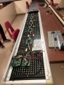
Ive got an old led screen / sign that i'd like to get working. Hopefully someone can put me in the right direction. It seems to be in good shape and is properly build so i'd hate for it to end up in the garbage. Got it for a couple bucks from a guy who got it from a guy.. There is no sticker or plate with a manufacturer name, so i have no idea how to run this thing. Here are a couple of shots from the unit:


Here's what i found out sofar:
-It has 32x252 red leds, divided over 6 boards, 1 controller board, powered by 2 20A 5v psu's.

One of the 6 led driver boards:

-When i power it up, its showing: multimedia led 2005. Now there is a company called multimedialed.com that sells displays, but they dont have any info on old signs on their website. They do have a pdf file on their 'Multimedia 2MPRO' signage software (http://www.multimedialed.com/radiate/radiateUploadFiles/2MPro_User_Man.pdf). On page 23/24 it mentions the communication options, but it says they only use 232/485 or modem, not ethernet.

-There is an rj11 connector on the back for communication. And a dipswitch on the pcb to switch between RS232/485/Ethernet. I would prefer RS232, i can convert it using a MOXA Nport later if need be. No problem setting it to 232 but there is a 9 wire cable going from the pcb to the rj11 connector. Any way i can find out what the RX and TX wires are? (and i still need some software to run it to even know if the connection is working i guess..)


-When i take a closer look at the controller pcb it has a number on it, but google cant find any info on it. HXITC054.PCB. I tried searching for the names of the bigger components but they arent specific to this display.

There is also a little logo on it, looks like a capitol G to me, maybe someone will recognize it?

Hopefully someone has a helpful tip, thanks in advance! (Apologies if i spelled something wrong/weird, this isnt my native language.)
Here's what i found out sofar:
-It has 32x252 red leds, divided over 6 boards, 1 controller board, powered by 2 20A 5v psu's.
One of the 6 led driver boards:
-When i power it up, its showing: multimedia led 2005. Now there is a company called multimedialed.com that sells displays, but they dont have any info on old signs on their website. They do have a pdf file on their 'Multimedia 2MPRO' signage software (http://www.multimedialed.com/radiate/radiateUploadFiles/2MPro_User_Man.pdf). On page 23/24 it mentions the communication options, but it says they only use 232/485 or modem, not ethernet.
-There is an rj11 connector on the back for communication. And a dipswitch on the pcb to switch between RS232/485/Ethernet. I would prefer RS232, i can convert it using a MOXA Nport later if need be. No problem setting it to 232 but there is a 9 wire cable going from the pcb to the rj11 connector. Any way i can find out what the RX and TX wires are? (and i still need some software to run it to even know if the connection is working i guess..)
-When i take a closer look at the controller pcb it has a number on it, but google cant find any info on it. HXITC054.PCB. I tried searching for the names of the bigger components but they arent specific to this display.
There is also a little logo on it, looks like a capitol G to me, maybe someone will recognize it?
Hopefully someone has a helpful tip, thanks in advance! (Apologies if i spelled something wrong/weird, this isnt my native language.)
")