Idea review - precise 5V reference with current boost

Thread Starter

MrSoftware

Joined Oct 29, 2013
2,280
Would someone be nice enough to critique an idea. I've been out of the hardware game for a few years and a bit rusty and want to make sure I'm not overlooking something silly. ;)

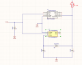
My requirement is a 5v reference with 0.1% tolerance that can sustain 5mA, but with the ability to surge 80mA at >3.5V for a few mSec to startup the load, and is short-tolerant. My idea is a 5V reference in parallel with a 5V regulator, separated by a diode. The regulator will supply the bulk current to start the load, then when the load stabilizes at 5mA, the voltage will rise to 5V and the voltage drop across the diode will essentially disconnect the regulator, allowing the reference to provide the precise voltage. I've attached a screenshot of the schematic.

The reference here can provide 10mA at 5V with 0.1% accuracy, the regulator can provide 150mA with ~2% accuracy. Both are short tolerant.

Am I overlooking any reason why this wouldn't work?
 

Attachments

ronsimpson

Joined Oct 7, 2019
4,851
It looks good to me.
the ability to surge 80mA at >3.5V for a few mSec to startup
Your regulator is 5.0V Then lose 0.6V in the diode. That looks good. So, there will be about 0V across the diode most of the time. The diode; 1N400x can be 1 through 7. 1=50V, 7=1000V. I might look for a low leakage diode, but I don't have a good reason why. I would have used a 1N4148 because we use million of them.
 

panic mode

Joined Oct 10, 2011
5,399
i do not see how that would work... if the load current exceeds that of REF5050, then output of regulator would kick in but only after voltage drop due series diode. in other words, this would be useless.

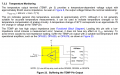
if you want output that can provide precise output and handle more current than REF could do on its own, you need to buffer that output, not bypass it with some voltage regulator. details are in the datasheet.
here they tell you all you need to know about buffering temperature output but same idea applies - get low drift, zero offset opamp that can handle load current.

1792290964831.png
 

MisterBill2

Joined Jan 23, 2018
28,485
The protection against shorted circuit overloads neds to be UPSTREAM from the regulation part of the system. The short-term overload could be ppast the capacitors, AFTER that regulator scheme.
 
Last edited:

crutschow

Joined Mar 14, 2008
38,909
The short-circuit current of the REF5050 is 25mA.
So that should give a startup time of <5ms for the 10µF load.
Is that not fast enough?
 
Last edited:

Ian0

Joined Aug 7, 2020
13,306
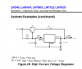
How about this circuit? It's from the LM340 datasheet, but it will work with any regulator.
Screenshot from 2026-10-18 18-12-24.pngIf the current is less than Vbe/R1 the regulator works as normal.
If the current is more than that, then the transistor starts to pass current.
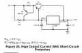
Unfortunately, it's no longer short circuit protected. You need an extra transistor for that:
Screenshot from 2026-10-18 18-15-27.png
 

WBahn

Joined Mar 31, 2012
33,309
i do not see how that would work... if the load current exceeds that of REF5050, then output of regulator would kick in but only after voltage drop due series diode. in other words, this would be useless.
Why? He only needs tight regulation for loads up to 5 mA. For loads greater than that, he's stated that it's fine as long as it doesn't go below 3.5 V.

If he wanted to further minimumize the voltage droop, he could use Schottky diode or use a regular that is set to just under 5 V + the diode drop.

I'm more concerned about the behavior during "start up". Does that mean when power is first applied to the system as a whole? If so, the start-up behavior of both regulator and the reference need to be taken into account.
 

Reloadron

Joined Jan 15, 2015
7,975

WBahn

Joined Mar 31, 2012
33,309
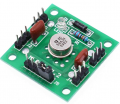
AD584 Voltage Reference 4 Channel 2.5V / 5V / 7.5V / 10V High Precision Voltage Reference Module

I have used these modules and they are as stable as a rock. Jumper selectable for Vout. I use a 12 VDC input but they work on less. I also recall only paying a few USD $$ as to cost.


Changing the position of the jumper, you can get different output voltages.

The output voltage is divided into four ranges 2.5V, 5.0 V , 7.5V and 10.0V

Ron
The TS may or may not be able to use a module in their application, but it's something for them to consider.

I'll definitely take your word for how well it works, but the pictures and description are very confusing (written by a five year old Chinese-speaker, perhaps?) and incomplete.

1792346336678.png
Perhaps you can answer based on the documentation you got or your experience.

How do you select the different Vout options? The labeling is not too clear, but maybe that's just a matter of alignment of the screen legent (are we seeing the copper showing through the board, given how faint it is?). I'm guessing the labels are supposed to be between pins and the jumper is placed to bridge those pins?

What are the three pins on each of the side jacks. One appears to be labeled GND. What are the other two?

Where is power applied? The description only states, "Corded Electric" and "12 volts_of_direct_current".

What is the accuracy and output current? Are the output channels isolated, or are they just tapped off the same outputs?

I've taken a look at the AD584 data sheet and it says that the maximum error of the 5 V output if 15 mV for the J version. That's 0.3%, which is 3x what the TS says they need (the TS might need to consider what they actually need, versus want). The K version is closer, but not quite there.

It also says that the input voltage needs to be 2.5 V greater than Vout and that, while it can deliver 10 mA at 25°C, it's only spec'ed to provide 5 mA over the temperature range. That's probably not a big concern for the TS's needs, but something to consider.
 

Reloadron

Joined Jan 15, 2015
7,975
The TS may or may not be able to use a module in their application, but it's something for them to consider.

I'll definitely take your word for how well it works, but the pictures and description are very confusing (written by a five year old Chinese-speaker, perhaps?) and incomplete.

View attachment 372377
Perhaps you can answer based on the documentation you got or your experience.

How do you select the different Vout options? The labeling is not too clear, but maybe that's just a matter of alignment of the screen legent (are we seeing the copper showing through the board, given how faint it is?). I'm guessing the labels are supposed to be between pins and the jumper is placed to bridge those pins?

What are the three pins on each of the side jacks. One appears to be labeled GND. What are the other two?

Where is power applied? The description only states, "Corded Electric" and "12 volts_of_direct_current".

What is the accuracy and output current? Are the output channels isolated, or are they just tapped off the same outputs?

I've taken a look at the AD584 data sheet and it says that the maximum error of the 5 V output if 15 mV for the J version. That's 0.3%, which is 3x what the TS says they need (the TS might need to consider what they actually need, versus want). The K version is closer, but not quite there.

It also says that the input voltage needs to be 2.5 V greater than Vout and that, while it can deliver 10 mA at 25°C, it's only spec'ed to provide 5 mA over the temperature range. That's probably not a big concern for the TS's needs, but something to consider.
Sure, these modules are actually pretty decent. I am not sure as to their current capability. I have left them for a week and zero drift. In the image foreground we see a jumper on the J5 connector, the jumper selects the Vout. OK we also have a J1 and J2 each a 3 pin connector where J1 and J2 are the inputs, J1 is positive and J2 is negative Vin. Each consist of 3 pins. J3 and J4 are the Vout where J3 is positive and J4 is negative Vout. We use the jumper on J5 to select a Vout voltage. When I messed with these modules I ran them for weeks at a time and the Vout was as stable as a rock. Measuring with an Agilent 34401A bench meter with a Vout of 5 volts selected I am currently reading 5.0029 volts. Set it up this morning before my first reply to this thread. Thinking back I want to say I bought 5 of these modules for about $10.00 USD or about $2.00 USD each. I originally used these as an external Vref for micro-controllers A to D. I have been powering mine with 12 VDC but as you read you need about 2.5 volts above your selected Vout. The ADS 584 is a can which I found amusing. Somewhere around here I have additional modules.

The infamous "somewhere" but I actually found three more in a box of stuff. OK here we go... :) All with Vout 5.0 volts selected and a 12 VDC Vin.

Module 1 5.0029 V.
Module 2 5.0019 V.
Module 3 5.0006 V.
Module 4 5.0015 V.

I should have another ? Heck I was happy to find the ones I found. :)

If I can be of any further help just let me know. I really have no documentation other than the data sheet you saw and keep in mind these are off the boat Chinese modules. :)

Ron
 

Thread Starter

MrSoftware

Joined Oct 29, 2013
2,280
Thank you everyone for the replies, there are some good ideas here. To clarify a few things:
- Startup time is unimportant, it's OK if it takes some time to charge the cap
- The startup configuration can be either load attached then power applied, or power applied then load attached. It has to work for both cases.
- The REF5050 that can supply only 10mA can successfully start the load by itself if the 10uF cap is allowed to charge before the load is connected, but this also has to work for the case that the load is attached before power is applied.
- The surge current is only required during startup. If it can reach 80mA at 3.5V+ then the load switches to steady-state which requires only 5mA
- This will be made in volume so price is important. The parts in my schematic are under $1.50 in volume which is acceptable.
- I used a single part in the past which worked great, but the part has become expensive and difficult to get in a timely manner. Unfortunately I have not been able to find a suitable single-part drop-in replacement, so this is my attempt to solve it.
 

WBahn

Joined Mar 31, 2012
33,309
Thank you everyone for the replies, there are some good ideas here. To clarify a few things:
- Startup time is unimportant, it's OK if it takes some time to charge the cap
- The startup configuration can be either load attached then power applied, or power applied then load attached. It has to work for both cases.
- The REF5050 that can supply only 10mA can successfully start the load by itself if the 10uF cap is allowed to charge before the load is connected, but this also has to work for the case that the load is attached before power is applied.
- The surge current is only required during startup. If it can reach 80mA at 3.5V+ then the load switches to steady-state which requires only 5mA
- This will be made in volume so price is important. The parts in my schematic are under $1.50 in volume which is acceptable.
- I used a single part in the past which worked great, but the part has become expensive and difficult to get in a timely manner. Unfortunately I have not been able to find a suitable single-part drop-in replacement, so this is my attempt to solve it.
If start-up time is unimportant, then where does the 80 mA figure come from? Why isn't 10 mA enough to successfully start if the cap it attached first? If it limits at 10 mA, that would only take 3.5 ms to reach 3.5 V.

What single part did you use in the past? That would help us narrow down the space.

It now sounds like cost and part count is a big factor. That would have been nice to know up front.
 

Thread Starter

MrSoftware

Joined Oct 29, 2013
2,280
Startup time is unimportant, but current is. The load is a black box to me, but experimentally it behaves like a circuit breaker that needs to be tripped to switch to steady state mode. If you don't provide enough current to trip it, it will sit there happily gobbling current all day. When the 10uF cap is charged prior to connecting the load and in parallel with the REF5050, the combined capacity is enough to trip it into steady state. But when the same circuit is powered after the load is attached, it just sits there gobbling current and never switches to steady state or fully turns on.

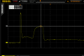
I am over simplifying the load a bit: my single test unit spikes at 73mA for ~2.4uSec then draws 40mA for another ~19uSec, then drops to 5mA steady state. The attached screen shot shows the current draw during startup. But the load design is out of my control and the tolerance on the load parts is pretty bad, so I want to design with a enough capacity to supply more current and for longer duration than is required by my single test unit. The prior part was MAX6165BESA+ and that part works very reliably.

Vcc is from a 9V battery, so it starts around 9.4V and the low battery warning is displayed at ~7.5V.

1792427417390.png
 

crutschow

Joined Mar 14, 2008
38,909
Given the low apparent cost of the ICs you have selected, your post #1 circuit may well be the lowest cost way to go, (assuming that's your primary consideration}.
 

panic mode

Joined Oct 10, 2011
5,399
Why? He only needs tight regulation for loads up to 5 mA. For loads greater than that, he's stated that it's fine as long as it doesn't go below 3.5 V.

If he wanted to further minimumize the voltage droop, he could use Schottky diode or use a regular that is set to just under 5 V + the diode drop.

I'm more concerned about the behavior during "start up". Does that mean when power is first applied to the system as a whole? If so, the start-up behavior of both regulator and the reference need to be taken into account.
of course but - what and where is the load? is it sink or source? voltage reference can do both (sink and source 10mA). voltage regulator cannot...
 
Top