Facebook
 Google
 GitHub
 Linkedin
Hello,
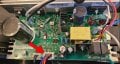
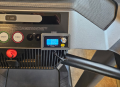
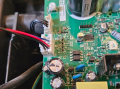
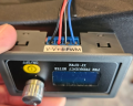
I have a NordicTrack T6.5 that was hit by the firmware update bug that bricked the console. I refuse to pay 500 dollars for parts for something they broke so here we are. I would like to convert the console into a simple up/down rocker for incline and a pwm dc motor controller for the belt. I have been going off the MC2100 diagrams found on this all about circuits forum. It had me questioning my design and wonder if I need to step down the voltage from 12V to 5V. Does anybody have any tips or schematics for the MC1658DLS? My idea was to do something similar to below using the 8 pin connectors from the HD6 on the 1648 board. Also, can the violet incline sensor wire be ignored or does the board require it?
Rocker Switch for incline
DC Motor