 Facebook
 Google
 GitHub
 Linkedin
Hi all,
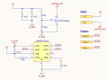
I recently came across a small 3-phase BLDC driver (Allegro A4949) circuit that has its IC ground separated from the power ground and connects the two grounds through a MOSFET. I'm new to electronics and wanted some insight to why this technique is used.
I have a schematic of the entire circuit for reference and attached it as an image.
I have read the datasheet for the A4949 and understand the component choices on each pin but cannot understand why the grounds are separated through a MOSFET. Furthermore, I am unsure about the type of the MOSFET, but when I search the markings, it shows as an N-Channel.
Any help would be appreciated. Thank you.
Attachments
-
 38.7 KB Views: 20


