 Facebook
 Google
 GitHub
 Linkedin
Hello all,
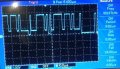
I am using an MPU9250 via I2C and used an oscilloscope to observe the I2C waveforms. The SCL and SDA waveforms are attached. SCL seemed ok being square enough. But SDA waveform doesn't go to zero completely rather there are small steps where it goes to zero. Just want to understand if this is normal behavior, if not what might be causing this and how to address it. I am using 1k pull ups and the bus speed is 400khz.
I am using an MPU9250 via I2C and used an oscilloscope to observe the I2C waveforms. The SCL and SDA waveforms are attached. SCL seemed ok being square enough. But SDA waveform doesn't go to zero completely rather there are small steps where it goes to zero. Just want to understand if this is normal behavior, if not what might be causing this and how to address it. I am using 1k pull ups and the bus speed is 400khz.
Attachments
-
 113.7 KB Views: 16
 -
 107.4 KB Views: 16


