Facebook
 Google
 GitHub
 Linkedin
Hello,
I would like to ask you two questions in one post, as they are related to I2C and the same PCB.
1) I2C Microcontroller protection. I am using a development board to communicate by I2c with my custom PCB, where there are I2C expanders and power monitors. The problem is that after some time using it, usually days or weeks (not using it every day), the I2C port of the development board stops working. I still can use the dev. board and I2C with other pins, but not the original ones. I didn't give much importance at first, but recently, I have used another custom PCB to communicate with the first custom PCB, getting the same result, but this time the PCB is much more expensive than the dev. boards.
Do you know what can be the reason? Do I need to protect it with series resistors or clamp diodes? If so, could you give more details? I can't risk blowing up another PCB.
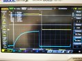
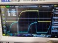
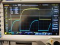
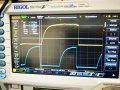
2) Quality of the signal. The communication works because I can enable signals and read data from power monitors, but I wanted to double-check whether the signal shown below with the oscilloscope is a typical one. There are like incompletes pulses or not sure what it is. Could you please help with this?

I have to design a new iteration of PCBs, so I would like to correct the mistakes done so far.
Many thanks in advance
I would like to ask you two questions in one post, as they are related to I2C and the same PCB.
1) I2C Microcontroller protection. I am using a development board to communicate by I2c with my custom PCB, where there are I2C expanders and power monitors. The problem is that after some time using it, usually days or weeks (not using it every day), the I2C port of the development board stops working. I still can use the dev. board and I2C with other pins, but not the original ones. I didn't give much importance at first, but recently, I have used another custom PCB to communicate with the first custom PCB, getting the same result, but this time the PCB is much more expensive than the dev. boards.
Do you know what can be the reason? Do I need to protect it with series resistors or clamp diodes? If so, could you give more details? I can't risk blowing up another PCB.
2) Quality of the signal. The communication works because I can enable signals and read data from power monitors, but I wanted to double-check whether the signal shown below with the oscilloscope is a typical one. There are like incompletes pulses or not sure what it is. Could you please help with this?
I have to design a new iteration of PCBs, so I would like to correct the mistakes done so far.
Many thanks in advance