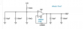
I want to modify this circuit to run on REF gnd.

MisterBill2

Joined Jan 23, 2018
28,011
What has not been explained at all to us is what the intended goal of the project is. The TS has decided what the intended hardware is and then is asking us to make it work without correcting the show-stopping problem. And certainly the choices for powering and biasing have created a show stopping problem, in that it will not work in this real world. And no amount of believing otherwise will change that. An op-amp will not output a voltage above it's positive supply voltage, nor a voltage below it's negative supply voltage.

High-pass and low-pass Filters in series, if done correctly, make very good band pass filters, or even band-stop filters. So if you start with a high-pass filter with a 400 Hz cutoff (3 dB point) and then feed the output into a low pass filter with a 600 Hz cutoff point, you will get a 500 Hz band-pass effect.
 

Thread Starter

Maglatron

Joined Nov 3, 2023
154
So why are you using the EARTH GND symbol?

View attachment 308962
because the 12v in needs to be grounded to the actual ground of the battery
What has not been explained at all to us is what the intended goal of the project is. The TS has decided what the intended hardware is and then is asking us to make it work without correcting the show-stopping problem. And certainly the choices for powering and biasing have created a show stopping problem, in that it will not work in this real world. And no amount of believing otherwise will change that. An op-amp will not output a voltage above it's positive supply voltage, nor a voltage below it's negative supply voltage.

High-pass and low-pass Filters in series, if done correctly, make very good band pass filters, or even band-stop filters. So if you start with a high-pass filter with a 400 Hz cutoff (3 dB point) and then feed the output into a low pass filter with a 600 Hz cutoff point, you will get a 500 Hz band-pass effect.
so I am going to have a mic thats connected to a variable gain pre-amp run from a 9volt
for the 9 volt for the pre-amp I will use a voltage divider Vout = Vin x (R2/R1+R2)
pick R1 to be 10k
9V = 12V x (R2/10k+R2)
solve for R2 = (9V x 10k/12V-9V)
R2 = 90k/3V
R2 approximatly 30k!
(which uses a voltage divider from the 12Volt source)and this signal is going to be put through a 32Hz filter that uses virtual ground, this is because it only requires one power source in this case 12V then that filtered frequency needs an envelope detector to give an analog varying DC voltage this uses the same virtual ground the signal then goes to pin 5 of the LM3914 and the Rlo is connected to the virtual ground I need help to set the Rhi to 10V
 

MisterBill2

Joined Jan 23, 2018
28,011
OK, so now we have a description of an arrangement of items for some unstated purpose. Which has been mentioned since I started my response.
And now a bit of information about "Vref"!! For this sort of application it is incorrect. The term should actually be Vcc/2, which serves to provide a mid-point for the signal voltage being amplified. For all audio signals in a single-supply amplifier arrangement itis not optional, it is mandatory. Without that, the very best possible is 50% clipping at all amplitudes, if the circuit is even able to function at all.
The output of an op-amp, as I stated once before, can not exceed beyond the supplied voltages. It does not happen!!
THAT is the reason that the non-inverting input gets biased at Vcc/2. Vref is not a good description. It is used to describe a reference voltage for regulator circuits and others that must compare some variable voltage to the constant voltage to know the difference voltage.
 

Thread Starter

Maglatron

Joined Nov 3, 2023
154
could you explain any clearer what you mean please
Vout_ref = 1.25×(1+R1/R2)
10V = 1.25×(1+R1/R2)
solving for R1/R2
R1/R2 = (10V/1.25)−1
R1/R2 = 8−1
R1/R2=7
choose specific resistor values that satisfy this ratio
R1=1kΩ and R2=7kΩ
 

MisterBill2

Joined Jan 23, 2018
28,011
could you explain any clearer what you mean please
Vout_ref = 1.25×(1+R1/R2)
10V = 1.25×(1+R1/R2)
solving for R1/R2
R1/R2 = (10V/1.25)−1
R1/R2 = 8−1
R1/R2=7
choose specific resistor values that satisfy this ratio
R1=1kΩ and R2=7kΩ
It is not clear where the equation presented came from, but it is incorrect for an audio amplifier.
Besides that, an audio amplifier does not use a reference voltage.
The zero signal DC level of a single supply audio amplifier is Vcc/2, because that allows a symmetrical variation above and below the no-signal point. Evidently the circuit shown in post #1 is not an audio amplifier. And the attempt to dispense with the excessivly complex circuit below "What's This" in post #1 has been a total waste of resources.
The required voltage, (Vcc/2), is easily provided by a simple network of two equal resistors and a polarized capacitor from the junction of the resistors to the supply negative. The equal resistors being in series between V= and the supply common (zero volts) point often called GROUND,
The large-value capacitor between the Vcc/2 point and the supply common connection is what prevents any audio signal from affecting the voltage on that line.
As for the "dancing bar graph described in post #24, the function has been exhaustively developed under the title of "color organ", with probably over a thousand different implementations, between 1965 and 1980. Implementing it with LEDs and LED meter IC devices has also been done in many examples.
 

Thread Starter

Maglatron

Joined Nov 3, 2023
154
the equation relate to the bar graph LED's driver the LM3914 Vout ref pin seven is connected to pin 6 the Rhi pin and you set it's voltage with resistors in this cas to 10v and the virtual ground at 6V so this means slighly above 6v and the first LED of 10 will light and at 10v they all light
 

MisterBill2

Joined Jan 23, 2018
28,011
OK, two different reference voltages. A bit of confusing terminology. For the amplifiers and filters it would be Vcc/2 to designate the voltage.
 

MisterBill2

Joined Jan 23, 2018
28,011
If that device is an op-amp, then this is a BUFFERED Vcc/2 circuit which would be used in applications where some current might be drawn. BUT I did not look it up to see what the device actually is. BUT it is NOT what you need. For the bar-graph display all you would need are the two 10K resistors and that 10μF capacitor. The Vcc/2 will be from the junction of the two resistors. 12 volts at the top, 12 volt common at the bottom.
Check the Schematicsforfree website, category LIGHTING, sub category DISCO. quite a few color organ circuits that include filtering for the different frequency bands. That is the part to understand. Much simpler than the narrow filters you show.
 

MisterBill2

Joined Jan 23, 2018
28,011
How narrow a frequency band does each filter need to have?? The older color organs divides the spectrum into high, middle, and low frequency bands. The much more elaborate ones had four frequency range bands. It almost looks like this package is intended to sense specific notes.
 

Thread Starter

Maglatron

Joined Nov 3, 2023
154
How narrow a frequency band does each filter need to have?? The older color organs divides the spectrum into high, middle, and low frequency bands. The much more elaborate ones had four frequency range bands. It almost looks like this package is intended to sense specific notes.
specific frequencies yes
 
Top