I want to make a capacitor meter

Thread Starter

q12x

Joined Sep 25, 2015
2,244
I want to make a capacitor meter. The one that measure capacitance from 1pF up to as high as possible, because I know is a limit range.
What do you suggest ? Ideally a circuit that you built already. Or that you had your eyes on it.
It can be an old circuit, or new. Ideally a DMM circuit would be interesting, as long as I understand it. At least the capacitor meter part of it.
It is the first one I make, and I want it to be interesting.
That's it, Thank You !
 

Thread Starter

q12x

Joined Sep 25, 2015
2,244
Are you looking for ideas on how to do it?
yes, a simple one in the beginning. Because I have the tendency to complicate things.
also as diverse ideas as they can be, the better.

I would suggest that you do it in ranges. It would be difficult to do in a single range.
My idea is to do it with a GPIO pin and a resistor. You charge and discharge the capacitor and measure frequency.
Agree, w the ranges.
That's it? that simple?

My first question: How accurate does it need to be??
Second question: should it measure any other variable , like leakage or dissipation factor?
first :
well, if we are doing it in ranges, the first ones should start from 1pF, or the closest down we can go. That's the accuracy.
If we can make it that sensitive, then the rest of the values up, will be very accurate.
second:
ideally yes, but Im dedicated and happy w only capacitance measuring.

So in conclusion, stick the cap on the GPIO pins + a series resistor (10R?, 100R? or through experimentation?) and that's it? The rest is the code problem? Is what you are saying.
 

Wendy

Joined Mar 24, 2008
23,814
The simplest I can think of is a 555 timer where the resistor is used to calibrate (does not have to be a 555 timer). Any R C oscillator would work. From there you use a frequency counter, and it should give you a direct readout of the capacitance. I will be back tomorrow with more ideas how to do one from scratch.
 

panic mode

Joined Oct 10, 2011
5,236
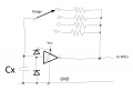
this is one idea. use some inverter with Schmidt trigger (inverter or NAND or NOR or 555 or whatever) to make an oscillator. use different resistors to make different ranges. use MCU to measure frequency or period depending on range. from that and chosen range you can calculate capacitor value.
1789859001995.png
 
Certainly an RC oscillator can allow finding the frequency, but other variables also affect it. So it is a valid choice, but not all simple. Accurate frequency measurement is common, as are good oscillator circuits. Not simple, but well understood.
Of course, that is not a direct measurement of capacitance, so math is required. Using a known oscillator frequency to determine the reactance at that frequency can also work, and may be simpler to make work well.
 

Wendy

Joined Mar 24, 2008
23,814
First of all, what you are looking at is a A to D converter. Back when I was in college they showed me the way a DVM does it. a linear waveform similar to what is shown.
D to A Converters #1.png

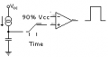
A constant current heating a capacitor will form a linear waveform.the duration of which is is the a measure of the capacitance. Interestingly, a DVM uses a much similar principle to measure voltage. You measure duration with a circuit similar to this:

duration measurement.png

Add a comparator to create the pulse you want.and you get a duration proportional to the measurement.

capacitance meter..png

The key is the digital to analog conversion, which is always tricky. I find it interesting that it almost always depends on a linear slope to do the conversion.
 
Last edited:
There is another method of measuring capacitance over a wide range. That method uses a constant amplitude signal passed thru the capacitor, and measures the amplitude of the signal after passing thru. Since the impedance of a capacitor is inversely proportional to the frequency, that mentod can work quite well.
 
How about a (Wheatstone) bridge circuit? Variable capacitor in one leg, large calibrated dial, opposite capacitor under test. Fixed resistor opposite potentiometer to select ranges. Needs a bit more thought!
 

Thread Starter

q12x

Joined Sep 25, 2015
2,244
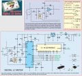
With reference to MisterBill2's post #11. There was a design based on that principle in Everyday_Practical_Electronics magazine March 2010.
I found it, and is at page 11. Here is full rezolution circuits inside that magazine. The top one is the similar to MisterBill2 one. Very interesting !!!! I like it can do C and L too !!!
Screenshot_3 copy.jpg

How about a (Wheatstone) bridge circuit?
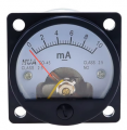
I like the idea very much actually. Also I have this brand new type of meter: 1789991681683.png from Aliexpress, of various ranges. I already build with this type of meter, a simple and very cute & elegant ESR meter (I may add): maxresdefault.jpg ---All my design!! modeled and mindstorm it inside my 3D application then in reality from literally bits glued together. Part2 you can see it here:
There is part1 next to it on youtube.
- But I need schematic, as simple and forward as it may look, draw it for me. I expect you may add some interesting features to it (or not). I know what a Wheatstone bridge circuit is especially for resistors, not capacitors, although I think I saw something somewhere too, but I can not pinpoint it.
Is a very nice idea !
 
Last edited:
- But I need schematic, as simple and forward as it may look, draw it for me. I expect you may add some interesting features to it (or not). I know what a Wheatstone bridge circuit is especially for resistors, not capacitors, although I think I saw something somewhere too, but I can not pinpoint it.
Is a very nice idea !
As is often the case, when I have an idea, I usually find that someone has been there before. This is disappointing and reassuring in roughly equal measure!
https://electricalacademia.com/instrumentation-and-measurements/capacitance-bridge-circuit/
You'll need an AC source - a 555 astable would be fine. My thinking was to make Cx a variable capacitor with a big dial so values can be read off it and the potentiometer the same to switch ranges. Using an analogue null meter is good. If Rq is a log pot with dial marked in decades you should be able to measure across a number of ranges.
 
Top