I want to make a capacitor meter

ronsimpson

Joined Oct 7, 2019
4,837
I now see post #17 shows the same project. Sorry about that.
---------------------------------------------------------------------
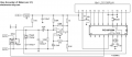
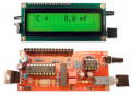
Here is a link to a capacitance meter I built many years ago. meter It will not measure large 1000uF caps. It is very good at small caps. I checked it against my $5000.00 meter and it is good. I can tell the difference between a 1pF and a 1.1pF cap.
I got my meter as a kit, but I see them on Amazon as a finished product.
1790004491248.png

From the may capacitance meters have built or purchased, I use very different methods for the small caps and the big caps.
If you really want good readings at 1.00pF you cannot use wires from the meter to the cap. I can post a picture of how to do that. Just getting your hand near a 1pF cap will change the readings.
1790005013086.png
 

MrChips

Joined Oct 2, 2009
35,213
Having experimented with my original idea in post #20, I have reviewed my solution.
Because of the length of time needed to discharge the capacitor, this scheme would be better suited for a narrow range of frequencies.

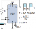
Instead, I propose to use a CMOS 555-timer circuit in astable mode.


1790084757685.png


You can probably get away with a single range using one value of R, covering 6 orders of magnitude.
As in the original scheme, measure the time for N cycles.

Capacitances greater that 10 μF tend to have higher percentage tolerances, 10% or 20%. Hence you can afford to reduce the value of N without having to change the value of R.
 

Thread Starter

q12x

Joined Sep 25, 2015
2,245
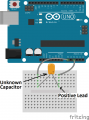
Here is a link to three Arduino capacitance meters. I made the two-pin one. It's very simple to make and it works extremely well. I modified the software to take care of built-in self capacitance so it measures below 10pF.
How to Make an Arduino Capacitance Meter (circuitbasics.com)
-I finally decided to TRUST this very sketchy arrangement from your link, but it turns out to be quite brilliant and like you said,very simple to implement, both in hardware and software.
The last one on that web page, this one:
1790348100012.png
- Without any capacitor plugged in, meaning the pins were in air, the value it reads was 0.2pF, meaning the internal wiring capacitance, which Im very ok to leave it alone, not zero it in code. I can subtract it from the final result, its not a big deal, or leave it, it makes too small difference.
- I tested 360uF and it worked, with 2-3 seconds more delay than for smaller caps. But on 470uF is out of range.
- I've crossed over this circuit before, but I didnt trust it. Because you told me you test it and worked, that gave me the trust to try it too.
Now I'm at peace with it.
This concludes and answered my question ! It's a good thing I asked around, it always is.
Thank you ALL !
PS
-Ive also tested this circuit https://www.circuitbasics.com/arduino-ohm-meter/ for an ohm meter from the suggestion on the same web page. It also worked exactly as it was explained. And then I also made a diode and LED checker, showing the Vf for each , including schottky diode, beside rectifier diodes. This program I made it myself and it is using a series resistor like in the ohm meter circuit, but with different code. I have to switch between the 2 modes to measure correctly. But the idea was to test them directly on the mcu pins, which is a very interesting way to measure and the very first time for me.
 
Last edited:

panic mode

Joined Oct 10, 2011
5,303
as the URL suggests those circuits are basic.
keep in mind that measuring something is one thing, getting accurate measurement is another.

for example resistance measurement that article starts with assumes that 5V rail is really 5V:

int Vin = 5;

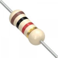
in reality it can be anywhere 4.8-5.2V and if powered by USB port, it can drop down to some 4.6V. fortunately that circuit is ratiometric so errors due supply will largely be cancelled. the other thing is to measure something, you need reference that is more precise. 5% resistors are not much of a problem if you measure them and know the value but the pictures show that he is using carbon resistors. they are crap when it comes to temperature changes. don't take my word for it, attach it to DMM and the blast some hot air at it and observe changes.
1790358227456.png


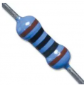
then do the same using metal film resistors. those are also typically 1% or better.
1790358348313.png

as the article states, reference resistor need to be reasonably close to value of measured resistor. they suggest replacing resistor and changing code every time you get different resistor to measure. that is nonsense. have couple of values (need GPIOs) as part of your tester and enables them as needed though code so you can autorange. also internal ADC of MCUs is poor (low res and noisy). in case of Arduino R3 it is only 10bit but R4 uses renesas MCU that has 14bit ADC. while convenient since already there, this pales in comparison with typical external ADC.

next, i see no protection on any of the MCU pins. internal protection diodes may be able to cope with light duty scenarios (low energy static) but no MCU is safe by itself. certainly connecting capacitor that is not discharged can cause damage. which is why any decent circuit will always have protection any IO pin that connects to outside world (via test leads for example). using current limiting and pair of low leakage diodes as shown before is a right thing to do.
 
I want to make a capacitor meter. The one that measure capacitance from 1pF up to as high as possible, because I know is a limit range.
What do you suggest ? Ideally a circuit that you built already. Or that you had your eyes on it.
It can be an old circuit, or new. Ideally a DMM circuit would be interesting, as long as I understand it. At least the capacitor meter part of it.
It is the first one I make, and I want it to be interesting.
That's it, Thank You !
If you are interested in using Arduino, you can follow this Capacitance meter tutorial. This is based on an Arduino Nano and a GLCD. This is one of the simplest types. It can measure 1 pF to 99 µF. You can replace the GLCD with a generic 16 x 2 LDC with proper coding and connections. While working on your project, you can also refer to this Capacitor converter for Unit conversion, checking expected readings, capacitor-code interpretation and choosing test components.
 

panic mode

Joined Oct 10, 2011
5,303
and like most similar pages lacks something important. in this case i see no mention where to get the Capacitance library that code relies on. and as previously mentioned, no protection, so charged cap would destroy MCU
 

MisterBill2

Joined Jan 23, 2018
28,411
Oh Wow!!! So far in this thread I have seen a whole lot of good ideas, and a couple of great ideas. My concern wit measurment schemes is STABILITY, so that the same part gives the same reading every time. IfI check it against a standard and it always reads the same, than I can know how close my readings will be. At the same time I like things to be simple.That is often the opposite of stable.
So here is mysuggestion, which is still another way: Put the capacitor as one element of a voltage divider. My reason is that good voltage accuracy and measurement stability are well understood and there is lots of information on how to di it accurately. And the associated resistor just needs to be accurate and stable, and that part is well documented.
The plan is to feed the voltage divider with a known voltage waveform at a stable known frequency, and know the voltage drop thru the unknown capacitor in series with the stable and known resistor.
The capacitive reactance will provide part of the voltage drop, and the known resistor will provide the rest of the voltage drop. And since the frequency can be very well controlled and easily known, since it does not change, figuring the capacitive reactance is fairly simple math. Holding thewavefor voltage constant is also fairly simple. The frequency can come fro a crystal oscillator, which would be very stable. And accurate stable voltmeters are quite common. So there is another scheme that can be very stable. Votage regulators are also able to be quite stable.
By having different frequencies available you can change ranges.
 

ronsimpson

Joined Oct 7, 2019
4,837
The plan is to feed the voltage divider with a known voltage waveform at a stable known frequency
You probably know what a wheatstone bridge is:
1790773106495.png
The internet (which is often wrong) think this is how you do capacitors. I would put the reference capacitor on one side with the unknown capacitor. On the other side the reference resistor and the variable resistor. In storage I have a Wheatstone bridge that dates to 1900. The frequency and voltage do not have to be stable. You are simply comparing the ratio of reference capacitor to unknown capacitor.
1790773493581.png
 

MisterBill2

Joined Jan 23, 2018
28,411
I have an an ancient EICO electronic bridge that does that. The downside is that to be fairly close it needs a fairly high voltage, plus that a capacitor with leakage resistance gives a wrong reading. AND, it is a challenge to accurately read the scale.on the balance pot.
 
Top