I want to control motor speed with capacitors

Thread Starter

mtalent

Joined Oct 2, 2017
30
Ok remember you guys Mark is not the sharpest tool in the shed for this kind of circuit work, so I can't be making this any more difficult. Maxes number of 5 triacs makes sense 3 for the caps switching and two to reverse the polarity to reverse motor. The burst fire switching will have to wait until version 2.0.

I hope you guys looked at my switch setup and approve, I don't want to blow anything up if I don't have too. I think it should work. I am looking at some push on wire connectors. one on my pcb (female) and male to connect after removing mechanical switch. I am hoping to just open up fan switch area cut out reverse switch and mechanical switch. Push the wires into a connector and connect to my pcb. close it all up nice and move on.

with the two switches I have I should be able to do low and medium going to try to have it done today ....wish me luck :)
 

Thread Starter

mtalent

Joined Oct 2, 2017
30
Just found out we are doing the 2017 Sacramento Home Show (next week). Just ordered a very cool outdoor caps controlled fan for demo. And 3 led down lights to control. App is stable (it's been running on an lg android all week without problem) I have to admit that I turned off the phones sleep function to see if it will stay working. I have a problem when phone sleeps and when user hits home button and puts app in background. I have the solution it is the android activity life-cycle methods just have to figure out exactly how to use them. woohoo
 

Thread Starter

mtalent

Joined Oct 2, 2017
30
Everything is done, this fan speed control was just a side thing I picked up on at the end. We have a prototype built for the louver control and led lighting control. If I can't get the fan speed part done in time we just won't use it. I am going to try though :)
 

Thread Starter

mtalent

Joined Oct 2, 2017
30
quick question can I switch the traics with 3.3v. My rf chip is 3.3 and I am getting a power supply. Should I get a 5v and step it down so I have both?
 

Thread Starter

mtalent

Joined Oct 2, 2017
30
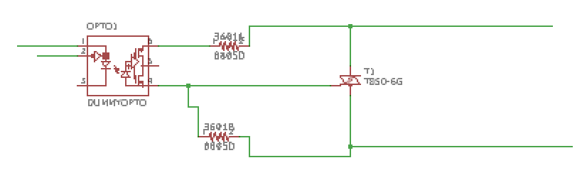
I just thought I would post that I was able to reproduce the pull chain switch in a capacitor type ceiling fan. Here is the circuit I used as the triac switch....


using MOC3162M with zero crossing trigger as the opto

I am using KTR10EZPF3600 360ohm resistors

also a T850-6G snubberless logic level triac.

You will notice there is no snubber, I used snubberless triacs, however after some research and speaking to those who know I ran one snubber directly across the motor (black to white) to make sure switching was smooth.

My circuit also has an H-Bridge that will reverse the fan. I put the whole thing on a 3 inch 2 layer pcb with smd parts so I could use both sides. the reasons the snubbers had to go was the board was getting too big.

As It stands I can open up the fan casing cut the appropriate wires off the mechanical switch and the two extra wires going to the dpdt switch(the other 4 wires on the switch are already going to the board) for direction control. I used slip on wire connectors so all you need to do is strip the wires and push them into the appropriate connector on the board. The whole thing takes about 10 minutes

the entire board fits in the original enclosure you put the top on and screw it shut and using mqtt and a mobile app I am able to completely control the fan.

However after finishing this I found another device someone had made that completely controls the fan without opening the fan up you just connect the black, white, blue wires coming from fan to the device and then connect the black and white from house power to the device. Set the fan on high with the light on and they are able to control fan speed using bluetooth (I prefer wifi because with bluetooth you are constantly having to disconnect whatever bluetooth device you currently have connected a to control another device) with wifi just open the app and make adjustments.

Anyhow I am thinking they are using PWM (any other ideas) to do it. I want to try to replicate this the most I can come up with is to set up a zero crossing detector then setting up a delay then firing the triac. In my mind I was thinking I could just use a zero crossing opto to detect the zero crossing take that information into a micro with an input pin and then programming in my delay and firing the triac circuit using an output pin. The idea seems to make sense in my head however it is hard for me to understand the why I want to do this and how long of a delay and am I still firing the triac with pwm????

Anyhow thanks for the help on the last project

Mark
 

Techohead

Joined Nov 23, 2020
11


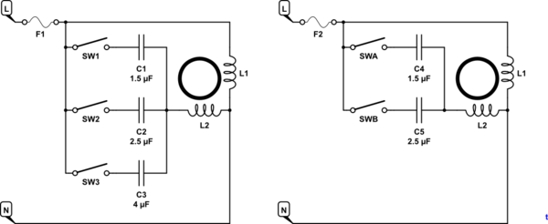
above left is the circuit I want to build

I am going to use electronic switches controlled by a micro-controller. My question is about the capacitor values, I am having a bit of a time finding the ones indicated

I was able to find this ..... CBB61 Ceiling Fan Capacitor for NEW TECH 5 Wire 4.5 uf+5uf+6uf 250 VAC....


My question is will this work to control fan speed, how does the increase capacitor values change the results. Also would this part work with 110 because it says 250VAC

I would like to use the recommended values but I am having a hard time finding them if anyone has any ideas

thanks
The circuit you are using is not a good idea. It will only transfer the load to the run winding, overloading it. Use the recommended start capacitor in series with L2 and put a capacitor in series with the whole lot. You will have to experiment with the value, as the inductive reactance of the motor will cancel out some of the capacitor reactance. try 10 to the 6÷2piFXc, where Xc=Mains voltage/motor current first, then adjust value to get the desired speed. Or use one of those triac control circuits.
 

Alec_t

Joined Sep 17, 2013
15,149
Welcome to AAC, Techohead!
It's a good idea to check thread dates before posting. This thread is over 2 years old, so the TS (thread starter) has probably lost interest in it.
 

MisterBill2

Joined Jan 23, 2018
28,062
?
Really?

Are you sure about that?

See @MaxHeadRoom ’s post (above)
An induction motor's speed is always a bit less than synchronous speed, because without the difference there is no current generated in the rotor. Consider that the tag on a 60Hz induction motor states the speed as usually 1750 RPM, synch speed would be 1800RPM.
And an induction motor's speed is also affected by the load and the supply voltage. So the capacitors will certainly affect the speed. But probably not with the circuit as shown.
 

shortbus

Joined Sep 30, 2009
10,049
An induction motor's speed is always a bit less than synchronous speed, because without the difference there is no current generated in the rotor. Consider that the tag on a 60Hz induction motor states the speed as usually 1750 RPM, synch speed would be 1800RPM.
And an induction motor's speed is also affected by the load and the supply voltage. So the capacitors will certainly affect the speed. But probably not with the circuit as shown.
Wow, that's safe for you. Commenting on something a poster that is no longer a member of the forum said, since he can't defend his thinking.
 

Techohead

Joined Nov 23, 2020
11


above left is the circuit I want to build

I am going to use electronic switches controlled by a micro-controller. My question is about the capacitor values, I am having a bit of a time finding the ones indicated

I was able to find this ..... CBB61 Ceiling Fan Capacitor for NEW TECH 5 Wire 4.5 uf+5uf+6uf 250 VAC....


My question is will this work to control fan speed, how does the increase capacitor values change the results. Also would this part work with 110 because it says 250VAC

I would like to use the recommended values but I am having a hard time finding them if anyone has any ideas

thanks


above left is the circuit I want to build

I am going to use electronic switches controlled by a micro-controller. My question is about the capacitor values, I am having a bit of a time finding the ones indicated

I was able to find this ..... CBB61 Ceiling Fan Capacitor for NEW TECH 5 Wire 4.5 uf+5uf+6uf 250 VAC....


My question is will this work to control fan speed, how does the increase capacitor values change the results. Also would this part work with 110 because it says 250VAC

I would like to use the recommended values but I am having a hard time finding them if anyone has any ideas

thanks
Ok, I did what any good engineer would do. I went and got a 3 speed fan and took it apart.

It all looks pretty basic, I removed three screws to open the area containing the switch and caps.


then I pulled out the caps and removed the chain activated switch for a closer look.


and the actual switch


Ok one of the gray wires goes straight to the motor, the other runs through the switch and is in switch position one. the red which is the lowest uf of 4.5 goes straight to the motor. I believe this has to do with what someone on another sight said "The fan might not like being powered without any cap connected. Leave the low speed cap always connected, and switch two additional caps in circuit (four speeds possible).
If you also want on/off, then use a relay in series with the fuse.
Leo..
"

So now we have the purple (5uf in position 3) and brown (6uf in position 2) with the black (load) and one of the grays from the capacitor pack in the mechanical switch. Now my question --- Are we just increasing the total capacitor value with each switch (meaning that for setting 2 (medium) the switch for the brown is closed) and then for high we leave the switch on the brown closed and close the switch on the purple. So for low we have 4.5 uf, medium is 10.5 uf and high is 15.5 uf.

I am going to make a schematic of my electronic switch configuration so you guys can let me know if I am understanding this right. My schematic skills are not that great but I will try

thanks
Mark

Max and cmartinez I want to understand what you guys are talking about but it is tough for me. My understanding of the pwm is that you limit the duty cycle of the pin so it is turning on and off quickly and since it is off for an amount of time the amount of voltage getting to the motor is less. However, I have a feeling there is more to it than that. I'll post the picture of the whole circuit so maybe someone can help explain.

Don't worry about the 250Vac. That is only the maximum voltage the cap. is designed to handle. The caps. will be switched in one at a time, or none for 'OFF', not paralleled as the current surge would damage the switch contacts. Depending on what size motor you are controlling, you might need higher value ones, especially if those ones were off a 240V fan, which would only take 1/2 the current. Leave the original start capacitor in place and put these ones in series with the whole motor, NOT the start winding only like in the above cct.
 

Techohead

Joined Nov 23, 2020
11
Ok I need help again, my diagram is nice and it is helping me but I am still a little confused trying to follow the power here.

just for a refresher here is the cap


in the pull chain mechanical switch seen below.


the house power black wire goes to switch position L

Brown wire from capacitor to switch position 2.

Purple wire from capacitor to switch position 3

Gray wire left side of capacitor pack goes to switch position 1

The other Gray wire from left side of capacitor pack goes directly to reverse switch

Red wire from capacitor pack goes directly to motor.

Ok my thinking is that the gray wire going directly to the reverse switch eventually makes it's way to primary coil

Red wire is going from capacitor pack to secondary coil no switch

Now I am having some problems with the purple, brown, gray wires going to switch. And how to include them in my electronic relay.

The second gray wire is not connected to a capacitor and there are two of them where would I connect this wire to my switches. I was originally thinking that I would switch house power to the brown and purple wires but then how does that get to the secondary winding.

The three place switch has house power and the gray wire and the purple and brown going in. I have been trying to find a switch wiring schematic but not much luck.

Maybe I connect the gray to the black and the purple to the brown (not likely but man I am killing myself here I don't understand the flow of the current through the caps pack).

I have two switches/relays in my setup which should work for this setup. because my thinking is low is both switches off, medium is one switch activated and high is both switches activated. When I cut the mechanical switch out I am going to have 4 wires and my switches allow 3 (so am I going to connect two of them together or am I wrong and I need another relay).

Any help would be appreciated thanks all
This is the circuit I would have expected.Fan Motor Circuit.pngCould you replace one of those pictures with one that shows all of the wires?
 

Techohead

Joined Nov 23, 2020
11


above left is the circuit I want to build

I am going to use electronic switches controlled by a micro-controller. My question is about the capacitor values, I am having a bit of a time finding the ones indicated

I was able to find this ..... CBB61 Ceiling Fan Capacitor for NEW TECH 5 Wire 4.5 uf+5uf+6uf 250 VAC....


My question is will this work to control fan speed, how does the increase capacitor values change the results. Also would this part work with 110 because it says 250VAC

I would like to use the recommended values but I am having a hard time finding them if anyone has any ideas

thanks
I figured it out. This is the circuit of your fanFan Motor Circuit.png
 

asrikerex

Joined Mar 6, 2020
1


above left is the circuit I want to build

I am going to use electronic switches controlled by a micro-controller. My question is about the capacitor values, I am having a bit of a time finding the ones indicated

I was able to find this ..... CBB61 Ceiling Fan Capacitor for NEW TECH 5 Wire 4.5 uf+5uf+6uf 250 VAC....


My question is will this work to control fan speed, how does the increase capacitor values change the results. Also would this part work with 110 because it says 250VAC

I would like to use the recommended values but I am having a hard time finding them if anyone has any ideas

thanks
first of all you need to know what is the maximum capacitor value of your fan. You might be ok to use 10% higher value capacitor then the original value. if you exceed this 10% tolerance you will burn L2 coils/capacitor coils/Running coils. Mostly fan coils is protected with 2amp 135C° thermal fuse. So if you really want to maximise the potential speed of your fan, you need to keep your eye on coils temperature, do not exceed 75C° operating temperature, other wise you going to face smell of burning coils insulation.
 
Top