I want to build a DC to AC inverter.

Thread Starter

Hextejas

Joined Sep 29, 2017
187
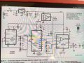
And am looking for a simple schematic.
My next series of lessons have me working with AC and for now I want to stay away from the mains.
So, I have a DC supply that can vary from 3-14 V
I need AC from probably 6V to maybe 24 and anything in between.
I have done a Google search and still am, but I trust y'all (<--Texas talk), a lot.

Thanks
George KG5TKY
 

Alec_t

Joined Sep 17, 2013
15,112
You might find it easier just to use a mains transformer with a multi-tapped secondary winding. This type was commonly used in old hi-fi systems, for example.
 

Thread Starter

Hextejas

Joined Sep 29, 2017
187
I found an old unlabeled, beefy wall wart by Matsushita. When I plugged it in it was putting out .75v dc. The connectors are alligator clips which I thought was odd. Strange output too.
So, is there some way I can figure out what it's specs are and maybe wire it backwards?
Another learning experience.
Plug DC into the AC side and see what comes out.
I wonder if I could run my dc through something that would generate a pulsating dc and see what the wart does with it.
 

Thread Starter

Hextejas

Joined Sep 29, 2017
187
I saw this schematic in QST magazine and, not being adept at reading them, wondered if it might be what I am looking for.
Apologies for the quality.

hextejas_IMG_0412_corr.JPG

Moderators note : removed moire effect using the GIMP
 

Attachments

Last edited by a moderator:

Papabravo

Joined Feb 24, 2006
22,068
I don't think so. The power level available from an audio oscillator will not be useful for powering anything. In this case you are creating a square wave out of the 74HC4040 and presumably something approximating a sinewave at the J1 output jack. By reading the datasheet for the MAX294 you can get some idea of the output power available. Without looking at the datasheet, your sinewave will be 5VP-P or 1.76 V-RMS. If the MAX294 can provide 50 mA-RMS you will have a whopping 88 milliwatts of output power.

EDIT: looked at the datasheet and could not find an explicit mention of output current or power.

You might want to consider something like this:
https://www.google.com/imgres?imgurl=http://www.electroschematics.com/wp-content/uploads/2010/09/12v-solar-power-inverter.gif&imgrefurl=http://www.electroschematics.com/6087/portable-solar-power-inverter/&h=635&w=758&tbnid=KAB-B7gdCebm_M:&tbnh=160&tbnw=191&usg=__myPHE3rTVqqGmzSkm_PvnFgAagk=&vet=10ahUKEwjUv6awq_3XAhVF5iYKHe9IBOIQ9QEISjAA..i&docid=T2zRPkATPx_gXM&sa=X&ved=0ahUKEwjUv6awq_3XAhVF5iYKHe9IBOIQ9QEISjAA

Alternately grounding the upper and lower legs of a center-tapped transformer connected to a positive DC supply is a common technique.
 

Thread Starter

Hextejas

Joined Sep 29, 2017
187
I need something to simulate a 60hz ac source. This seems to be able to do that.
Additionally I am curious to see what my exercise will do if it encounters greater than 60 hhz.
The exercise is meant to go from 110v, 60hz into 9v dc. So I have no clue if this will work.
I want to stay away from messing with 110v for a bit.
Plus I just love building stuff
 

Papabravo

Joined Feb 24, 2006
22,068
I need something to simulate a 60hz ac source. This seems to be able to do that.
Additionally I am curious to see what my exercise will do if it encounters greater than 60 hhz.
The exercise is meant to go from 110v, 60hz into 9v dc. So I have no clue if this will work.
I want to stay away from messing with 110v for a bit.
Plus I just love building stuff
So the schematic I showed you is a 1-chip oscillator, driving a pair of MOSFETS, driving a transformer. Pick a transformer with a reasonable conversion ratio, or better yet wind your own on a toroid that you select for say 3:1. So connect a +12V source to the center tap and you should get approximately 36VAC out. Of course there will be losses, and the current out will be 1/3rd of the current in. I could have a lot of fun with this project.
 

Thread Starter

Hextejas

Joined Sep 29, 2017
187
So the schematic I showed you is a 1-chip oscillator, driving a pair of MOSFETS, driving a transformer. Pick a transformer with a reasonable conversion ratio, or better yet wind your own on a toroid that you select for say 3:1. So connect a +12V source to the center tap and you should get approximately 36VAC out. Of course there will be losses, and the current out will be 1/3rd of the current in. I could have a lot of fun with this project.
Thank you Papa, that is precisely what I am looking for. Winding the torrid will be a great new project for me.

Is there any way that I could see what the output wave form looks like without investing in a scope ?
 
Last edited by a moderator:

bertus

Joined Apr 5, 2008
22,909
Hello,

When you want to use the MAX294 as filter, you will need to amplify the output as the MAX294 can onlty drive a 10K load.
Perhaps a power opamp like the LM1875 might do the job, as it has a max current output of about 4A.

Bertus

PS I cleaned up the picture in post #6
 

Papabravo

Joined Feb 24, 2006
22,068

Alec_t

Joined Sep 17, 2013
15,112
If the operation frequency is within the audio range (up to 20kHz) you could use a voltage divider to tap off a low-amplitude sample of the inverter output and feed the sample to the mic/line input of a PC sound-card. You can then monitor it using an audio processor such as Audacity (freeware).
 

Thread Starter

Hextejas

Joined Sep 29, 2017
187
I tried the Matsushita wall wart again for ac and it's putting out 6.5 v ac. Just for grins I switched the meter to dc and it also seems to be putting out 14.5 v dc.
Is that possible, that it puts out both?

Did you check if it was putting out AC?
 

ebeowulf17

Joined Aug 12, 2014
3,307
If you really want to build something for the sake of building it yourself, that's great, but if your primary goal is having an AC supply to experiment with, while staying safe, a basic step down transformer from mains will be cheaper, faster, easier, AND will give you a cleaner sine wave than many (most?) oscillator projects can.

If your concern is that you don't want a mains connected transformer because that means you have to wire something to mains, there are enclosed, safe transformer options in the form of pre made AC power supplies:

https://www.digikey.com/products/en...?sort=unitPrice-A&keywords=&tf_InStockOnly=on

https://www.amazon.com/Adapter-Transformer-1000mA-Straight-Female/dp/B00B8861IS

Again, I don't want to discourage you if you want to build your own inverter, but I thought you should know it's probably not going to be as efficient, cheap, easy, or effective as a simple transformer.
 

Thread Starter

Hextejas

Joined Sep 29, 2017
187
If you really want to build something for the sake of building it yourself, that's great, but if your primary goal is having an AC supply to experiment with, while staying safe, a basic step down transformer from mains will be cheaper, faster, easier, AND will give you a cleaner sine wave than many (most?) oscillator projects can.

If your concern is that you don't want a mains connected transformer because that means you have to wire something to mains, there are enclosed, safe transformer options in the form of pre made AC power supplies:

https://www.digikey.com/products/en...?sort=unitPrice-A&keywords=&tf_InStockOnly=on

https://www.amazon.com/Adapter-Transformer-1000mA-Straight-Female/dp/B00B8861IS

Again, I don't want to discourage you if you want to build your own inverter, but I thought you should know it's probably not going to be as efficient, cheap, easy, or effective as a simple transformer.
Thank you ebeo, your suggestion about a purchase makes sense and I want the build experience too. So I think that I will do both and use the purchased product as a reference.
I had a closer look at the upcoming lessons and they deal with making a voltage doubler, tripler, and quadrupler. Those kinds of voltages scare me on an open breadboard.
 
Last edited:

Thread Starter

Hextejas

Joined Sep 29, 2017
187
Papa, a few questions if you please.
1) it looks like those 3 schematics are all the same ? Any reason for posting it thrice ?
2) as I did more reading on this, I read about pins 1-3 of CD4047b. I read that it determines frequency.
I also read about a formula for calculating the frequency as f = 1/8.8RC.
Plugging in the numbers on the schematic of R=120k, C=100nf, I get a freq of .0528 ?
I have no idea if that means anything or is significant,
I think that I want to be close to 60hz, and if i read the formula accurately, it computes to
R=1k, and C=2mfd.

And now I am off to learn how to wind a toroid.

Thanks again
 

Papabravo

Joined Feb 24, 2006
22,068
Papa, a few questions if you please.
1) it looks like those 3 schematics are all the same ? Any reason for posting it thrice ?
2) as I did more reading on this, I read about pins 1-3 of CD4047b. I read that it determines frequency.
I also read about a formula for calculating the frequency as f = 1/8.8RC.
Plugging in the numbers on the schematic of R=120k, C=100nf, I get a freq of .0528 ?
I have no idea if that means anything or is significant,
I think that I want to be close to 60hz, and if i read the formula accurately, it computes to
R=1k, and C=2mfd.

And now I am off to learn how to wind a toroid.

Thanks again
It is a cut and paste thing, and I only get a single image when I click on the hyperlink. Why do you think it is 3 separate links?

I'll bet you didn't consider the units when you made your calculation. The period of the output is 4.4RC. The frequency is the reciprocal.

\(4.4\;*\;120\;\text k\Omega\;*\;100\;\text nF\;=\;0.0528 \text seconds\)

\(\frac{1}{0.0528\;\text seconds}\;\approx\;18.93\;\text Hz.\)

I can't tell if the intention was to use 60 Hz. or not
 
Last edited:

Thread Starter

Hextejas

Joined Sep 29, 2017
187
It is a cut and paste thing, and I only get a single image when I click on the hyperlink. Why do you think it is 3 separate links?

I'll bet you didn't consider the units when you made your calculation. The period of the output is 4.4RC. The frequency is the reciprocal.

\(4.4\;*\;120\;\text k\Omega\;*\;100\;\text nF\;=\;0.0528 \text seconds\)

\(\frac{1}{0.0528\;\text seconds}\;\approx\;18.93\;\text Hz.\)

I can't tell if the intention was to use 60 Hz. or not
I have a mistake somewhere and will find it tomorrow.
Re the link, yeah it is just one. It was just so big, and it worked from either end.
My bad, I'll do better tomorrow.
 
Top