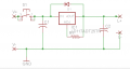
You are posting your files in .sch (schematic) formats and a .zip file containing files that go with the software you created the files in. Unless people can open the files they are useless. It's like me posting a .pdf file and nobody has Acrobat Reader to open the files. For a schematic save the file to maybe a graphics format like .jpg or .png ad then post it.
how to do that. I cant upload brd file. and if I print screen and save it as png. you cant see the details in eagle. so how to do the upload. I am confused.
all the files I uploaded before were Zip files. so it need Zip software to open them. but there is no way I can upload brd file. I don't know what to do.
OK, I think you are doing this in Eagle. Should that be correct here is what you can do. Open your .sch (schematic) file in Eagle. From File on the top choose Export and then Image from the Export options. In the Export Image dialog box check Clipboard and then OK. The image has been saved to the clipboard. Have Microsoft Paint open, Microsoft Paint is a general Windows program, any photoshop program will work. In MS Paint choose Edit and Paste. Your schematic image is now in MS Paint. Choose File and Save As and select to save the image as a .png file. You can do the same with your other files. That should help.
While the LD1117-ADJ is the chip to use, your board layout is incredibly awful. The most glaringly horrid mistake of all is you have mounted an undersized SMD current limiting resistor immediately underneath the part of the regulator's mounting tab on the opposite side of the board. What are you trying to do, cook your poor regulator to death? You should have NOTHING under that chip other than a copper pour and thermal vias. Next off are the circuit traces which are far too thin for power applications. Then there is the output capacitor and reverse protection diode. You do NOT want to have a cap on the output of a constant current regulator for two reasons. First it throws the feedback compensation loop off potentially resulting in the regulator oscillating and second, the first time your laser diode gets disconnected either through manually tinkering with it or a transient bad wiring connections the diode will let out the magic smoke. Why? As soon as you take the load off a constant current regulator the voltage on the output shoots up, charging up the cap on the output, and as soon as that diode is reconnected your constant current regulator will become a capacitive discharge diode fryer. That said, since you shouldn't have a cap on the output there is no need for a reverse protection diode. Finally your layout is asking for potential ground loop issues.
If it were me, I'd use the low dropout regulator, a good 50v rated 10uF XR7 MLCC cap or maybe tantalum, ditch the tactile switch in favor of a latching push button DPDT, and maybe even set up some sort of DIP switch array so I can set my output current as at the current your intending to push will exceed the maximum wattage ratings of most trim pots. I might even go so far as to put a semi-high value bleed down resistor in parallel with the input cap to make sure the regulator quickly completely powers down when you switch it off.

 Facebook
 Google
 GitHub
 Linkedin