Facebook
 Google
 GitHub
 Linkedin
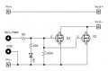
Folks, have been working on the project and I'd appreciate any help with checking if everything wired correctly and if there's anything needs to be added or is redundant.
Project is straightforward: PIR sensor activates solenoid valve. There's switch for PIR sensor with indicator light and a button that turns on solenoid right away.
I tried assembling the above without switch/button/led and it seemed to be working. However I noticed that 12V input for Mosfet module needs to be connected to the left side of the breadboard as it loses voltage if it is on the right side (to 5V approx) as if PIR sensor acts a resistor. I tried using diode between PIR module and breadboard but in the end couldn't connect the button and the switch.
Furthermore, I have doubts on:
- the need for pull-down resistor(s)
- wiring of button and placement of diodes