In my attachment in post #2 I explained how the transistors are biased so that they do not produce crossover distortion. But class-B always has crossover distortion. Real audio amplifiers use class-AB with the transistors biased a little.
Here again is my attachment about biasing the transistors:
Your assignment is teaching you how NOT to make an audio amplifier.
"Class B" is defined as the active device conducting for 180° of the signal. If it conducts for 179.9°, it is "Class C", and if it conducts 180.1°, it is "Class AB". Add to that the fact that the B-E junction of a transistor does not have an infinitely sharp knee, and you can see that a true "Class B" amplifier is a practical impossibility.
suppose ... the ohmic (electro-dynamic) speakers . . . seem to be parametrized at their lowermost frequency usually 20 or 40 Hz
where the series R is almost the name impedance and the XL is filling it up to "name resistance" . . . say for Z = 16Ω the R=15 and thus XL≈5.6Ω → L=XL/(2π·f)≈44mH(20Hz) --or-- 22mH(40Hz)
your second TF-s secondary winding has to match that Z=16Ω . . . if you increase the L component of it your frequency response goes worse
so use the speaker's impedance components or a lesser inductance . . . the R of the secondary goes however in series with your speaker also the translated non-parasitic Z of the primary so there must be a loss compenzation as U/u=i/I=N , "UI=ui" , R=U/I , r=UI/i²=R/N² R=rN²
basically the 16V DC supply is insufficient for compensating the losses and providing enough power to speaker
so if i dont forget something then you need to drive the primary by U → vect(Z.pri) "+" vect(vect(?R.sec?) "+" vect(Z.spk))·N² -- it's because the energy is transferred from XL to xl . . . anything else (also core-magnetic and other parasitic losses) are the part of the total load as seen from TF input side
so you have to get 16W to z.spk or to Z.spk as part of Z.spk/Z.tot or z.spk/z.tot
the xl.sec is not included since you ENTER your NRG to XL.pri and it converts it's IU=P.@XL to iu . . . if i remember correct
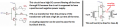
This circuit is no longer a complementary circuit, it is a regular push pull power stage withforward bias applied to both bases. A TIP31 would work quite well here but the bias may need to be adjusted a bit. A complementary stage driven from a transformer will be more complex in that the PNP will need a negative forward bias while the NPN side will need a positive forward bias. I can do it with the collectors tied and using an LM301 op-amp, but at that point it would be rather clear that outside help was involved. And since this is a take-home exam that may not be allowed.
It does look like not many read that post that described what was actually requested. And as for the class of operation, in at least some circles it is a bit looser than saying that "class B is only exactly 180 degrees." The challenge of driving a complementary pair with a center tapped transformer is that each transistor must be biased towards conduction, where the base current to collector current ratio becomes much more constant. If the emitters are tied to each other it becomes impossible to do with a single transformer winding that gives a low resistance connection between the bases.
If the arrangement is reversed so that the pair is connected as collectors tied, and the PNP emitter connects to V+, and the NPN emitter connects to V-, then it can be done, with each transistor base bias set by a resistor from emitter to base and a resistor from base to supply common. Then the input transformer would be capacitor coupled to each base, and the center tap connected to supply common, also. The bias resistors would need to be selected so that each transistor was just starting to conduct a bit.
There are other ways the same arrangement could be done but it would be very clear to whoever evaluates your work that you had outside help with the design.
I never really understood the home work request. I got: input and output transformers. After that I got lost.
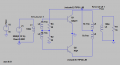
Most people think center tapped transformer but the following circuit with two transformers would work. (add bias?)
Your new biasing with two 30 ohm resistors causes the NPN transistor to be conducting a very high base-emitter and collector-emitter current all the time.
The example I showed of a class-AB amplifier used a diode so that the two NPN transistors conduct only a small current to avoid crossover distortion.
The PNP transistor is connected with backwards polarity and its base-emitter is conducting a very high current all the time.
When the two transistors are connected as a class-B amplifier with no bias then the two transistors are still conducting a very high current all the time.
Circuit on the right desperately needs a capacitor in-between the input transformer and the two Bases. OR The bottom end of the input transformer could be set at 1/2 supply.
The title is ".... class B push pull amplifier with center tapped transformers..." So that is what we all built at first. Now we are trying to understand the choice of NPN & PNP transistors.
I think we all don't know the real question.
Circuit on the right desperately needs a capacitor in-between the input transformer and the two Bases. OR The bottom end of the input transformer could be set at 1/2 supply. View attachment 195847
The end of the input transformer SECONDARY that is shown commoned must instead connect to the junction of the two emitters. And why has the negative supply shown earlier been replaced with a common connection? Wishing it would work will not make it work!
I never really understood the home work request. I got: input and output transformers. After that I got lost.
Most people think center tapped transformer but the following circuit with two transformers would work. (add bias?) View attachment 195840
This circuit is not the same as the complementary circuit shown in post #15 That post shows two supplies, one positive and one negative. That does make quite a difference. In fact, it makes a very big difference in the idling current, and in how the bias must be set, and how the load must be connected. The result is that it becomes quite a challenge to bias both the NPN and the PNP transistors slightly into conductionwhen both the bases and the emitters are tied to each other. Adding capacitors makes it possible but then it may not be direct coupled.
Not knowing what is in the teachers head, causes me to not want to work on this any more.
From experience:
The teacher said in class some thing that we did not hear at AllAboutCircuits.
The teacher thought he said ……. but he did not say that.
The student thought he heard …….. but was texting at the time.
The hand out contradicts what the teacher said.
The question is clear only to the teacher.
We can not remember who said "center tapped transformer" first.
Push Pull has too many versions. Which one?
After spending 50 hours on this question the teacher through out the question because no one got it right.
Teacher never really built one of these.
Audio amp or RF amp? Never said. Implied? Did the teacher ever say "50 or 75 ohms = RF, 8 ohms=audio"?
This list could go on, but I need to stop thinking on this!
The teacher just gave the question which I posted earlier. And he did not give the load resistance. But just said to build a class B push pull amplifier with transformer coupled at both input and output with a load current of 1A using TIP 31 and TIP 32. I think now the question is quite clear. I said center tapped earlier because I thought it was the only way to incorporate a transformer in the circuit. I am sorry if it misguided you.
 Facebook
 Google
 GitHub
 Linkedin