I need help with a Zener diode circuit.

Thread Starter

nikola1912

Joined Oct 25, 2017
24
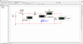
Hi, so like the title says I need help with a Zener diode circut. I have this report I have to do for my electronics class and the teacher in that class can't really explain us, the students, what to do for that report the best, so practicly no one understood him what we had to do. In class we did this circuit on the picture bellow. I think that he was trying to tell us that we had to move the slider on the potentiometer and then we have to record the values (on a peace of paper) on the Ampmeter and the Voltmeber which are "connected" to the Zener diode. Then we would have to make some sort of a graph.
I need your guys' opinnion on this. I'm really confused and scared that I might get an F. An explenation of the circuit would really help, like a step by step explenation.
The pictures below are:
1. Zener diode circuit which we made in class, which I recreated home (the program is Multisim);
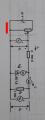
2. a picture of the Zener diode circuit in my book (please ignore that red line).
 

Attachments

MaxHeadRoom

Joined Jul 18, 2013
28,617
I think he wants to demonstrate the effect of the final circuit load on the conduction state of the zener with a series limiting resistor of 300Ω (R2).
And with a corresponding increase of the DC supply.
IOW at some point of the supply output, the final load may drop sufficient voltage across R2 that the zener may not come into effect?.
Max.
 

WBahn

Joined Mar 31, 2012
29,976
It's really hard for us to guess what your instructor wants you do to for your report when all you are really telling us is that you don't know what he wants you to do for your report. We aren't mind readers.

Your guess seems pretty reasonable, as least as far as a major part of the work is concerned. Figure out and plot the values of those four quantities for a range of potentiometer settings. You might plot the values you expect to see based on an analysis of the circuit as well.

As for explaining to you, step by step, what that circuit does and how it behaves, how does THAT have anything to do with helping you understand what the instructor is asking you for? That sounds more like asking us to write your report for you.
 

Thread Starter

nikola1912

Joined Oct 25, 2017
24
It's really hard for us to guess what your instructor wants you do to for your report when all you are really telling us is that you don't know what he wants you to do for your report. We aren't mind readers.

Your guess seems pretty reasonable, as least as far as a major part of the work is concerned. Figure out and plot the values of those four quantities for a range of potentiometer settings. You might plot the values you expect to see based on an analysis of the circuit as well.

As for explaining to you, step by step, what that circuit does and how it behaves, how does THAT have anything to do with helping you understand what the instructor is asking you for? That sounds more like asking us to write your report for you.
Thanks, I'll probably do that. About "explaining step by step", I wrote it wrong. I wanted someone to explain what these Ampmeters and Voltmeters were showing the values of. I get myself confused just by looking at the picture. I don't understand why the Ampmeter U3 shows almost the same value as the Voltmeter U4. Or why the Ampmeter U2 is always showing 0, I tryed changing the slider on the potentiometer, every indicator changes its value exept the Ampmeter U2.
 

Thread Starter

nikola1912

Joined Oct 25, 2017
24
I think he wants to demonstrate the effect of the final circuit load on the conduction state of the zener with a series limiting resistor of 300Ω (R2).
And with a corresponding increase of the DC supply.
IOW at some point of the supply output, the final load may drop sufficient voltage across R2 that the zener may not come into effect?.
Max.
I'm really trying not to be annoying with the lack of my knowlage, but please, could you explain to me what " the effect of the final circuit load on the conduction state of the zener with a series limiting resistor of 300Ω (R2) " means.
Also what does IOW mean.
 

MaxHeadRoom

Joined Jul 18, 2013
28,617
IOW = In-Other-Words.
The load itself will obviously result in a drop in voltage due to the load current through the series resistor, at some point of the potentiometer, this voltage drop is going to be below the zener conduction point.
Max.
 

WBahn

Joined Mar 31, 2012
29,976
Thanks, I'll probably do that. About "explaining step by step", I wrote it wrong. I wanted someone to explain what these Ampmeters and Voltmeters were showing the values of. I get myself confused just by looking at the picture. I don't understand why the Ampmeter U3 shows almost the same value as the Voltmeter U4. Or why the Ampmeter U2 is always showing 0, I tryed changing the slider on the potentiometer, every indicator changes its value exept the Ampmeter U2.
An ammeter (not ampmeter, but perhaps in your native tongue that's how it would best translate) shows the value of the current flowing through the ammeter. So if you put an ammeter in series with a component, it shows the current flowing through that component.

A voltmeter shows the value of the voltage across the voltmeter. So if you put a voltmeter in parallel with a component, it shows the voltage across that component.

A voltmeter and an ammeter NEVER show the same thing -- because one is a current and the other is a voltage. Trying to say they are showing the same value would be like saying that someone's height is the same as the volume of a container of milk -- comparing them is fundamentally meaningless.
 

WBahn

Joined Mar 31, 2012
29,976
I'm really trying not to be annoying with the lack of my knowlage, but please, could you explain to me what " the effect of the final circuit load on the conduction state of the zener with a series limiting resistor of 300Ω (R2) " means.
Also what does IOW mean.
What is the basic point of a circuit like this? Why would someone even try to use it? As you move the potentiometer through it's range of settings, does the circuit always accomplish this goal, or does it stop doing so at some point. If so, try to explain WHY it stopped doing what it is intended to accomplish at that point.
 

MuPlusSigma

Joined May 22, 2014
15
I'm concerned that you might not have your circuit set up correctly. Based on your Screenshot_4.png, I think your voltmeters should not be adding a load to your circuit. They should have infinite resistance, not 10 ohms. As the circuit is shown in Screenshot_3.png, the voltmeters are having a huge effect on the circuit.

The ammeters are good, with a resistance very near zero. I'm assuming the software won't let you use a resistance of zero, so what you have is fine. With zero resistance on the ammeter, there is no voltage drop across the meter and therefore you can measure the current without affecting the circuit.

For the voltmeters, you want a high resistance. The software probably doesn't let you use infinity, so 1e012Ohm should work well enough. With high resistance on the voltmeter, there will be almost no current through the meter and therefore you can measure the voltage without affecting the circuit.

It's just an educated guess, but I think you need to change your voltmeters before you collect your data.
 

Thread Starter

nikola1912

Joined Oct 25, 2017
24
I'm concerned that you might not have your circuit set up correctly. Based on your Screenshot_4.png, I think your voltmeters should not be adding a load to your circuit. They should have infinite resistance, not 10 ohms. As the circuit is shown in Screenshot_3.png, the voltmeters are having a huge effect on the circuit.

The ammeters are good, with a resistance very near zero. I'm assuming the software won't let you use a resistance of zero, so what you have is fine. With zero resistance on the ammeter, there is no voltage drop across the meter and therefore you can measure the current without affecting the circuit.

For the voltmeters, you want a high resistance. The software probably doesn't let you use infinity, so 1e012Ohm should work well enough. With high resistance on the voltmeter, there will be almost no current through the meter and therefore you can measure the voltage without affecting the circuit.

It's just an educated guess, but I think you need to change your voltmeters before you collect your data.
I'll probably change them but the real problem to me is that I don't even know what data I'm suppose to collect. Thanks anyway.
 

Thread Starter

nikola1912

Joined Oct 25, 2017
24
An ammeter (not ampmeter, but perhaps in your native tongue that's how it would best translate) shows the value of the current flowing through the ammeter. So if you put an ammeter in series with a component, it shows the current flowing through that component.

A voltmeter shows the value of the voltage across the voltmeter. So if you put a voltmeter in parallel with a component, it shows the voltage across that component.

A voltmeter and an ammeter NEVER show the same thing -- because one is a current and the other is a voltage. Trying to say they are showing the same value would be like saying that someone's height is the same as the volume of a container of milk -- comparing them is fundamentally meaningless.
Thanks that clears things up alot. But I still don't understand why ammetar U2 is always showing 0.
 

Thread Starter

nikola1912

Joined Oct 25, 2017
24
IOW = In-Other-Words.
The load itself will obviously result in a drop in voltage due to the load current through the series resistor, at some point of the potentiometer, this voltage drop is going to be below the zener conduction point.
Max.
How do you think I should put that in graph?
 

WBahn

Joined Mar 31, 2012
29,976
I'll probably change them but the real problem to me is that I don't even know what data I'm suppose to collect. Thanks anyway.
You might give some thought to the impact that those low resistances are going to have on the operation of your circuit until you make them something reasonable.

Thanks that clears things up alot. But I still don't understand why ammetar U2 is always showing 0.
Let me say this again for emphasis: You might give some thought to the impact that those low resistances are going to have on the operation of your circuit until you make them something reasonable.

What is the nominal voltage of the zener?

No current will flow through it unless the voltage across it is at least that much.

What's the voltage shown on U1?

Is there ANY chance of the voltage across the diode being greater than the zener voltage of that diode?

With the resistance of the voltmeters being only 10 Ω, how much current must be flowing in U3 when the voltage across the zener diode is 10 V?
 

hobbyist

Joined Aug 10, 2008
892
May I suggest something, please, if you are taking electronics courses, so as to make a career of it, then instead of going into a frenzie about why meter readings are showing things you know it should not be showing, instead take advantage of the situation, and do what electronics technicians and designers do. They start from scratch, keep the original circuit on file, so you can refer back to it.

Make a copy of this circuit and begin taking it all apart, disconnect everything,and delete them off so the simulator doesn't get confused.

Now using your understanding of ohms law ect...
First do a quick calculation of the voltage that would be seen at the midpoint of the pot to ground.
Then build the circuit and test and see if the voltage is shown on the voltmeter in the simulator.
If its not, then look into the simulator to find a fix.
If it shows proper voltage, then begin to add the next components in the loop, add the 300ohm in series with the 1K load, then again calculate what the voltage should br across the load (1K).
Build and simulate, if voltages show wrong again find a fix with the simulator.
If voltages show proper value, then experiment to make sure you are getting proper meter readings, instead of putting the zener in there put a 1K resistor in parrallel with the load, then calculate the amount of current that would flow through that branch, if the meter shows differently then your correct calculation, then you need to attend to the simulator to find a fix for that problem.

If the meter shows proper readings, you are now ready to replace the resistor with the zener, then do it all over again, the simulator could be whats at fault.

That's how you go about these kind of problems in the electronics field.
When you build circuits, you will always come across eronious meter readings, thats where you have to go to the procedure of starting freom scratch and building and testing one stage at a time until you find the problem area in the circuit design.

I'm sharing this with you for your benefit of how to work in the electronics field with non simulated circuits.
 
Top