I need help SCR Pre-regulator control loop

Thread Starter

BigD61

Joined Nov 8, 2014
20
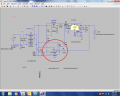
I need help with developing a control loop for a SCR controlled power supply. My circuit is based on a construction article published in Poplar Electronics written in the 80’s by G.R. Baumgras. I use a series of one shot timers to control the firing of the SCR where the original circuit used uA 723. The purpose for the design is to provide a pre-regulated voltage source for a precision voltage power supply. The pre-regulator greatly reduces the power waste of the precision regulator voltage drop when supplying low voltage at a high current level. I need help with developing the control loop. As the power supply output capacitor is loaded the operating point need to shift to keep the pre-regulator around 5 to 6 volts higher than the precision voltage level. The set point is dynamic and varies from 1 to 5 volts. I need help with developing a circuit that will offset the set point to maintain the desired pre-regulator voltage under varying load conditions.

Present circuit functionality: Vp= pre-regulator voltage, Vo = Precision Voltage Out, Vc = Voltage control to SCR trigger circuit.

Vo Vp Vc

0 10 4.20

7.5 14.6 3.94

13.7 20.6 3.582

20 25.6 3.204

25 28.62 2.91

The above chart is for a 130 ohm load.
When operating the pre-regulator set for 12 volts and 130 ohm load the required Vc is 4.00 volts. When loaded to 18 ohms, Vp drops from 12 volts to 10.65 volts. Changing Vc from 4.00 to 3.733 to bring Vp back to 12 volts. Using an differential amp will work to detect voltage unbalance between Vp – Vo, however this output is zero when balanced. How can I use this error to sum with the set point (Vc) to offset the Vc?
I just need ideas, I can/will do the research.
I have schematic for SCR trigger and general Block Diagram both in pdf format. Neither will upload to this forum, error message is " The upload is empty ... file name". Both file open with Adobe reader XI, file size is 88K and 13K. This is a common problem/issue for me, what am I doing wrong?
 

Thread Starter

BigD61

Joined Nov 8, 2014
20
Here it is. Note the the tracking offset is what sets the operating point (Vc). This circuit and the Tracking error are functional, the SCR control block is what I need help with. The operating point (Vc) moves with the setting of the precision power supply voltage. The circuit need to modify this voltage (VC) which control the 555 pulse width. Phasing requires the Vc to go down as Pre-regulator voltage drops due to power supply load current. Decreasing Vc cause the SCR to fire earlier along the trailing edge of the rectified 120 Hz thereby dumping more energy into pre-regulator filter capacitor. The SCR control work very well, manual setting of Vc will allow setting of the output voltage any value from peak dc to zero. I really appreciate idea to automate the control.
 

Attachments

ronv

Joined Nov 12, 2008
3,770
Maybe a couple more questions:
What is the AC input voltage (Peak)?
What are the min and max output voltage?
Min and max output current?
What does the rest of the circuit look like?
Have you considered a pwm pre regulator?
 
Last edited:

ronv

Joined Nov 12, 2008
3,770
Ahh, I think I understand your question now.

This is how I did it with a budget switcher.
The difference in input to output voltage is set with the zener to either on or off. I suppose you could use 3 of these to set your trigger levels.
 

Attachments

Thread Starter

BigD61

Joined Nov 8, 2014
20
Still looking for help, this is a old power supply built into work bench. Power supply works just fine. The pre-regulator is an enhancement, so I really do not want to start over. After all I thought this forum was about helping with electronic questions/problems. Once again I need some ideas to design loop control for output voltage that is variable by requirements.
The set point voltage varies from 1 to 5v which controls the pulse width and in turn control the turn on of the SCR to charge power supply capacitor. This set point voltage needs be be varied to maintain the charge on the PS capacitor. I need a circuit to sum the set point voltage with the error voltage that tracks the set point. (Set point +/- 200 mV is my SWAG). An opamp voltage follower summed on the non inverting pin should give correct phasing, however when offset error circuit is balanced its output voltage is 0, output of set point is current sinked through the summing resistor of the error amp and summing stage out is way off desired set point voltage. I will continue to work out a solution, I just looking for that SPARK.
 

ronv

Joined Nov 12, 2008
3,770
It is not clear what you want to do. You may understand your terms but I do not.
Is not what you want to do is maintain 4 or 5 volts between the input and output of the linear regulator so it doesn't run out of head room or dissipate to much power ?
If that is your objective the circled part of the schematic will tell you if it is higher or lower than the zener voltage, so should work for 3 steps with some added logic.
 
Last edited:

t_n_k

Joined Mar 6, 2009
5,455
I notice you appear to have incorrectly annotated the 4538 A & B pins. Inputs A are pins 5 & 11. Inputs B are 4 & 12.
Notwithstanding this likely error it seems the general operation is as follows:
With the half-wave rectified waveform going positive from zero, Q1 switches on causing U1a monostable to trigger. U1a output pin 7 goes low for a nominal 3msec interval. With U1a pin 7 going high at the 3ms point, Q2 switches on and triggers U2 555 timer (configured as monostable). U2 output duration is subject to the pin 5 control voltage which is the primary feedback control point. With feedback open, the 555 timer output pulse is nominally 2ms duration. If the AC supply is 50Hz, then the total delay would be the order of 5ms or half the rectified half cycle - somewhere near the peak value. If this is for a 60Hz supply, the 5ms total delay is just past the half wave peak.
With a control voltage applied to the 555 timer pin 5, the output pulse duration would vary. Less than 5V then less than 2ms - more than 5V then greater than 2ms. The high to low transition of 555 timer pin3 would trigger U1b (250us). The negative going edge of U1b pin 9 would trigger Q3 on for a short duration. Q3 on transition presumably triggers the SCR on. SCR remians on until the completion of the concurrent half-wave cycle.
The higher the value of control voltage Vc therefore means a lower charge let-thru to the pre-regulator dump capacitor.
Does that sound correct?
Does op-amp U4A pin 6 constitute the control to Vc via the diode and resistor?
You seem to have lost patience with the process on AAC very quickly. Did you expect us to come up with something specific in your time frame or ours? It takes time to digest the requirements and specifics of your system. So someone has to be firstly interested in what you are proposing and then has to come up with suggestions that comply with your constraints on the changes you would accept. All this at no cost to you....
 
Last edited:

ronv

Joined Nov 12, 2008
3,770
t n k, You must be a psychic. :) The driver for the control voltage pin doesn't even show on the schematic. :eek: But I bet your right. So his problem is really how to scale the control voltage based on the difference between Vin and Vout of the linear regulator?
 
Last edited:

t_n_k

Joined Mar 6, 2009
5,455
As you note ronv, the info we were given lacks some important detail. It may be possible to simply use the mean value of regulator input-output difference. Depends among other things on how much pre-reg ripple exists at the "worst case" loading. Would one need to ensure the instantaneous difference doesn't drop below a certain value. It may not be sufficient to simply use mean values. I would anticipate that some control function is also required to set the regulated output value. Perhaps a "fast" inner loop to set output and a "slow" outer loop to set regulator differential. Etc.....
If U4 is actually the control source one has a problem in terms of the available output positive region span. As far as I can see that op-amp has a positive supply rail of only +9V. Hence the usual output swing limitations would come into play w.r.t the control range. Hopefully the OP returns to fill in some of the gaps. But they seem to have lost patience with our intransigence.
 
Last edited:

ronv

Joined Nov 12, 2008
3,770
I suppose we could make some assumptions about the regulator and filter cap and see if we can make it work much better than a cycle skipper. Up to you.
I think the 555 is running at 5 volts so there may be enough swing.
 
Top