 Facebook
 Google
 GitHub
 Linkedin
Hello,
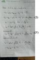
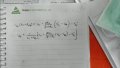
I am trying to derive an equation for this regulator, so I can put them on the excel file. Please refer to the attached image.
On the case that D1 is on (zener breakdown mode), and Q1 is forward-active, I derived the equation of iBB and found it strange.
From the equation, as RL goes higher, iBB becomes lower. I have simulated this circuit on LTSpice and got the result the other way around.
However, I checked the equation I derived step-by-step, and found nothing wrong.
Could you please help me check it?
Best Regards,
BlackMelon
Attachments
-
 156.8 KB Views: 26
 -
 362.9 KB Views: 26
 -
 144.4 KB Views: 23


