i need help here please

Thread Starter

gensal

Joined Dec 26, 2013
12
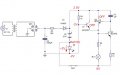
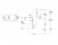
I need help in explaining this circuit attached in here.

I really need a complete and detailed current flow in this circuit. This is an emergency light, and I'm so confused why the current wont flow into the transistors whenever their is an AC supply. And what are the purpose of each of those resistors, capacitors and transistors. I badly need an explanation because I'm doing a report for this and i really cant understand it :(((

I'm still new in electronics. That's why if there would be someone willing to explain it, i will gladly appreciate it. Please help me. Thank you.
 

Attachments

Thread Starter

gensal

Joined Dec 26, 2013
12
Isn't Q2 backwards?

I believe the LED goes on and the bulb goes off when the AC is applied?
uuuh that cicuit is supposed to be an emergency light. so yeah it will turn off when it is in ac. but i really want a detailed explanation on why :confused:
 

Thread Starter

gensal

Joined Dec 26, 2013
12
And I really want to see some effort on your part to analyze the circuit and say what you think each part does...
i kinda understand the power supply part when their is a presence of ac supply. it chooses the ac supply rather than the dc as its source because it always chooses the bigger voltage. then it goes through the transformer where stepping down of the ac voltage then it rectifies, transforming the ac to dc supply then the capacitor where filtration of the signal happens and then the resistor (im not si sure of its function). after that is the diode, it is for safety purposes so that when the ac is absent, dc supply wont flow back to the power supply part. and here comes the confusing part. after the current went through the diode is a node where it should flow on both path: the rechargeable battery (it recharges the battery and the LED lights up) and the path to the resistor, i dont know what really happens after here because for the thought that the current flows through the resistor means there is a flow towards the base of the transistor, triggering it thus turning the transistor on (?)

sorry i havent really grasp the concept of transistor. all i know is that it just needs base current for it to turn on, letting the current to flow in the collector then to the emitter. so the first thing that came to my mind after considering that the current flows to the resistor is that the transistor turned on, and this will make the torch light illuminates. but ive done the prototype and no the bulb wont turn on when it is supplied w/ ac supply.

:confused: i am so confused.
 

Efron

Joined Oct 10, 2010
81
sorry i havent really grasp the concept of transistor. all i know is that it just needs base current for it to turn on, letting the current to flow in the collector then to the emitter. so the first thing that came to my mind after considering that the current flows to the resistor is that the transistor turned on, and this will make the torch light illuminates. but ive done the prototype and no the bulb wont turn on when it is supplied w/ ac supply.

:confused: i am so confused.
When confused you MUST go step by step.

I'll give you a clue. What happens when the LED lights on? Let's assume it will take about 2V across. In this condition, transistor Q1 will be OFF because the junction BASE-EMITTER will be biased in reverse (base more negative than emitter) - see schematic.

So, when do we reach the condition for Q1 to be ON? when this will happen?

Also I agree with Wayneh, to me Q2 is backwards !
 

Attachments

Last edited:

Thread Starter

gensal

Joined Dec 26, 2013
12
When confused you MUST go step by step.

I'll give you a clue. What happens when the LED lights on? Let's assume it will take about 2V across. In this condition, transistor Q1 will be OFF because the junction BASE-EMITTER will be biased in reverse (base more negative than emitter) - see schematic.

So, when do we reach the condition for Q1 to be ON? when this will happen?

Also I agree with Wayneh, to me Q2 is backwards !

eer yeah, Q2 is backwards. sorry, it's supposed to be a switching latch. thank you for noticing. :)

Q1 will only turn on when you apply a forward bias in its base because it is an npn transistor. am i right? did i answer the question? :confused:

but wait, i just want to clarify. this 2.5V for R4, is this because you of the voltage that will be supplied in the 2.5V battery?

and why is it -2V in the base of Q1?

sorry for so many questions. :(
 

Efron

Joined Oct 10, 2010
81
eer yeah, Q2 is backwards. sorry, it's supposed to be a switching latch. thank you for noticing. :)
Well it was Wayneh who noticed it first. So good to him!

Q1 will only turn on when you apply a forward bias in its base because it is an npn transistor. am i right? did i answer the question? :confused:
You need to go further. You're answer is technically correct, but in your application, when and why this will/would happen? Is it when you don't have ac source? why?

but wait, i just want to clarify. this 2.5V for R4, is this because you of the voltage that will be supplied in the 2.5V battery?

and why is it -2V in the base of Q1?
This is very IMPORTANT to understand, because it is the way it works (or not). Its ALL ABOUT REFERENCE.

Look at your transistor Q1. For it to go ON you need Vbase > Vemitter and obviously with respect to the same reference. So you must choose a reference (ground) for your transistor circuit.

For facility (to me), I chose the negative point of the 2.5v battery. So I can say that, with respect to that reference, the upper pin of R4 has 2.5V.

When the LED is ON (let's assume 2V across), the negative pin of the LED will have 2V more negative than the reference point (which means -2V).

And the negative pin of the LED is connected to the base of Q1, so for the same reference point, the base of Q1 is negative (-2V) with respect the its emitter (0V) and Q1 is OFF.

OK, now we know than when the LED is ON, none of the transistors will turn ON. And the LED can only be ON if there is ac source (the LED is ON thanks to sub-circuit C2, R3, D1, 2.5V Battery B1 and D2.

So now, what happens if the LED is OFF (open circuit)?

What are the new voltages on transistor side?
 

Thread Starter

gensal

Joined Dec 26, 2013
12
I chose the negative point of the 2.5v battery. So I can say that, with respect to that reference, the upper pin of R4 has 2.5V.
so the ac supply from the power supply that enters into the rechargeable battery doesnt matter/ affect the voltage of R4?

And the negative pin of the LED is connected to the base of Q1, so for the same reference point, the base of Q1 is negative (-2V) with respect the its emitter (0V) and Q1 is OFF.
that made sense, i didnt know that reference thing. :)

OK, now we know than when the LED is ON, none of the transistors will turn ON. And the LED can only be ON if there is ac source (the LED is ON thanks to sub-circuit C2, R3, D1, 2.5V Battery B1 and D2.
can i ask what's the main purpose for the R3 in there? is it a resistor for an RC filter? Or it has a different purpose?

So now, what happens if the LED is OFF (open circuit)?
when the LED is off, then there is no drop across it, making the voltage at the base of Q1 equal to 2.5V and this will definitely turn on Q1. sooo the collector will let the current flow towards the emitter and to the base of Q3, turning the latch ON. and then turning the bulb. :) am i right?
 

Efron

Joined Oct 10, 2010
81
so the ac supply from the power supply that enters into the rechargeable battery doesnt matter/ affect the voltage of R4?
Exact, this is a little bit tricky to see. Given that the emitter of transistor is depending on the negative pin of the battery, this is correct.

Because of this there is no interaction between ac part and transistor part.

can i ask what's the main purpose for the R3 in there? is it a resistor for an RC filter? Or it has a different purpose?
Take a look at the loop C2, R3, D1, 2.5V Battery B1 and D2;

At battery and LED side, if the LED is ON (about 2V across), the upper pin of battery will be 4.5V (2 + 2.5). -->> AGAIN THERE IS A REFERENCE HERE. IN THIS CASE I CHOSE THE NEGATIVE PIN OF THE LED = negative pin of C2.

But the LED is ON because there is ac source and then because there is current going through diode D1. If D1 is forward polarized, its positive pin will be 0.7V higher than its negative pin.

So, with respect to the reference point, the negative pin of the diode will have 4.5V and the positive 5.2V.

Knowing that, when the LED is ON, the voltage at the negative pin of D1 cannot change, R3 is there to avoid a burned diode D1 because of voltage drop bigger than 0.7V. So R3 has the role of protecting D1.

Indirectly, from this analysis it is deduced that the upper pin of the capacitor C1 must be greater or equal to 5.2V for the LED to light ON. Otherwise, the diode D1 will be not conduct.

when the LED is off, then there is no drop across it, making the voltage at the base of Q1 equal to 2.5V
This would be correct only if the current through R4 is 0, which will not. However, now, the base of Q1 is no more connected to anything but R4 (it is no more forced to -2V). You have then a normal biasing loop for Q1, as follows:

4.5V - R4 - base/emitter of Q1 - R5 - BL1 - 0V

Which will bring the base/emitter of Q1 to conduct.
 

Thread Starter

gensal

Joined Dec 26, 2013
12
Because of this there is no interaction between ac part and transistor part.
i just want to clarify this, there is no interaction because Q1 cant be turned on using ac supply in this setting right?

Indirectly, from this analysis it is deduced that the upper pin of the capacitor C1 must be greater or equal to 5.2V for the LED to light ON. Otherwise, the diode D1 will be not conduct.
Uh, just a weird question. cause i cant really explain it myself. after the current went through the battery, the LED will turn ON. does this mean that the voltage that lit up the LED came from the battery or the source?

This would be correct only if the current through R4 is 0, which will not. However, now, the base of Q1 is no more connected to anything but R4 (it is no more forced to -2V). You have then a normal biasing loop for Q1, as follows:

4.5V - R4 - base/emitter of Q1 - R5 - BL1 - 0V

Which will bring the base/emitter of Q1 to conduct.
Okaaay, i forgot about the resistor. :rolleyes: anyway now that the bulb is turned on, does this mean the latch here has no exact purpose? because you can simply light up the bulb without using the latch. :confused:
 

Efron

Joined Oct 10, 2010
81
i just want to clarify this, there is no interaction because Q1 cant be turned on using ac supply in this setting right?
Right.

Uh, just a weird question. cause i cant really explain it myself. after the current went through the battery, the LED will turn ON. does this mean that the voltage that lit up the LED came from the battery or the source?
From the source. Note that the battery and the LED are connected in opposite, so the battery will never be able to light on the LED.

So the ac source must be strong enough to overcome the voltage of the battery and diode D1.

Okaaay, i forgot about the resistor. :rolleyes: anyway now that the bulb is turned on, does this mean the latch here has no exact purpose? because you can simply light up the bulb without using the latch. :confused:
Yes you can without latch. But if you have ac source again, the bulb will also be switched off again.

The latch given by Q2, C3 and Q3 allows the bulb to be lit ON for ever once there has been a loss of ac source. For ever until you manipulate the switch SW1.

The latch works as follows (assumed Q2 in backwards !):
1/ Q1 switches ON and with that switching ON Q3.
2/ When Q3 is ON, the capacitor C3 charges quickly and reaches the necessary voltage to turn ON Q2.

3/ Once Q2 is ON, its base-emitter is maintained to 0.7V even if Q1 becomes OFF. This is thanks to C3.

4/ The only way to come back to the start point is by discharging C3. The only way to do it is to cut current from the battery through SW1.
 

Thread Starter

gensal

Joined Dec 26, 2013
12
From the source. Note that the battery and the LED are connected in opposite, so the battery will never be able to light on the LED.

So the ac source must be strong enough to overcome the voltage of the battery and diode D1.
perfect explanation, because ive been asking why is it that the battery placed reversely. so that's why :D thanks but im not done yet :)

Yes you can without latch. But if you have ac source again, the bulb will also be switched off again.

The latch given by Q2, C3 and Q3 allows the bulb to be lit ON for ever once there has been a loss of ac source. For ever until you manipulate the switch SW1.

The latch works as follows (assumed Q2 in backwards !):
1/ Q1 switches ON and with that switching ON Q3.
2/ When Q3 is ON, the capacitor C3 charges quickly and reaches the necessary voltage to turn ON Q2.

3/ Once Q2 is ON, its base-emitter is maintained to 0.7V even if Q1 becomes OFF. This is thanks to C3.

4/ The only way to come back to the start point is by discharging C3. The only way to do it is to cut current from the battery through SW1.
so sad, this is supposed to be an emergency light. where it turns on the bulb when there is no ac supply and off whenever it came back. but it will not turn off right? :( so does it mean that even if there is the presence of ac supply, the bulb is still lighting up?
 

Efron

Joined Oct 10, 2010
81
so does it mean that even if there is the presence of ac supply, the bulb is still lighting up?
Yes, that's correct.

I would say it is an emergency light but it also offers the possibility to register the fact that the ac source went off at least once (e.g. during night).

The latch circuit will still light up the bulb. A more beauty option would have been to turn ON another red LED.
 

Efron

Joined Oct 10, 2010
81
I mean what I say :)

The latch is done in Q2 and in your schematic, Q2 is connected to the bulb. But it could have been connected to other thing (e.g. another red LED).

So, in this case, the bulb will turn ON or OFF depending only on Q1, which will turn ON or OFF depending on the ac source.
 
Top