I suggest you do a bit of research for each type of wave generation in turn. The easiest waveform to generate is a square-wave: the most difficult (if you want low distortion) is a sine-wave.
You can use a feedback type astable multivigrator with integrator to get a square-wave and sawtooth that's relatively independent of frequency.
You can then integrate the sawtooth to get a quasi sine-wave with a few percent distortion.
The problem is that the integrator sine-wave amplitude it inversely proportional to frequency.
You could, of course, add an AGC circuit to stabilize the sine-wave amplitude.
As noted, generating a sinewave is the most difficult part of the task.
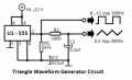
You can generate square using 555 timer ic or 741 opamp circuit diagrams you can find online. Giving this square wave input to integrator using 741 which you can find online again gives you Triangle wave and finally sine wave you can get it using 9-0-9 or any small rated transformer.
Or you can do like from 9-0-9 transformer you can get sine wave. Fed that sine wave to ZCD (zero crossing detector) circuit using 741 which gives you square wave again giving that square wave to integrator gives you triangle wave. Thus getting everything that you require in flow!..
I am making a pwm inverter and i have made almost 8 power supplies to power my opamp among which 3 are in working condition so things will be always going wrong in this projects. I would really recommend you to do Your project using 741ic. You will really learn how this stuff works. To begin prepare a power supply of +15 0 -15. Also you can get your desired frequency with changing RC and amplitude which would depend on supply that you are giving to your 741ic.
You can generate square using 555 timer ic or 741 opamp circuit diagrams you can find online. Giving this square wave input to integrator using 741 which you can find online again gives you Triangle wave and finally sine wave you can get it using 9-0-9 or any small rated transformer.
Yes, a 555 astable circuit can function at all frequencies between 10 Hz and 100 kHz.
No, that integrator idea will not work. First, a 741 does not have enough gain at 100 kHz to deliver any of the three waveforms with reasonable fidelity or distortion, or even amplitude. Second, the integrator circuit is basically a converter, not a generator. As the squarewave frequency varies from 10 Hz to 100 kHz, the amplitude will decrease by a range of 10,000 to 1. For a constant amplitude triangle wave as the input frequency changes, either the resistor or capacitor value has to change also. For example, there are 99,991 different integer frequencies in the stated range. If the integrator's resistor is fixed, you will need 99,991 different capacitor to have a constant output amplitude at each frequency.
No, any small rated transformer will not work. First, a transformer by itself will not convert a triangle wave into a sine wave. Second, I know of no transformer that will deliver a constant output over a four-decade frequency range.
Or you can do like from 9-0-9 transformer you can get sine wave. Fed that sine wave to ZCD (zero crossing detector) circuit using 741 which gives you square wave again giving that square wave to integrator gives you triangle wave. Thus getting everything that you require in flow!..
What you describe will work at exactly one frequency only. Since you don't say where the sinewave input to the transformer comes from, I can assume only that you mean to use the AC powerline. The entire circuit can be adjusted to work at the powerline frequency, but that is way less than 1% of the required frequency range.
If you want to buy a chip you can get one to do all three as mentioned elsewhere. What you did not supply yet though is the required specs for the distortion. Is it ok if there is a little distortion, say 5 percent?
There are a few different ways to do this if you dont want to use a microcontroller as the main generator, which is one of the modern methods.
1. Build a sine wave oscillator and buffer the output. Use a Schmitt trigger logic 'gate' for generating a square wave or just build a separate square and triangle generator. The sine wave oscillator gives the cleanest output when done right.
2. Build just the square and triangle generator (op amps) and use a non linear wave shaping circuit to shape the triangle into a sine. This is the way the analog function generator chips do it.
3. DSP. There are chips available that do sine but you have to send them the instructions on what frequency to generate and you usually need a microcontroller for this. This has the widest range of operation, from the sub Hertz range (like 0.01Hz) up to some 40MHz and the frequency for the sine is crystal controlled. So you get a very wide range and very good frequency stability.
 Facebook
 Google
 GitHub
 Linkedin