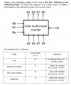
You have to do a synchronous counter design. Have you been studying excitation tables, transition tables, and Kmaps? Is clear supposed to be implemented? It's shown in the first picture, but not mentioned in the last post.
You have to do a synchronous counter design. Have you been studying excitation tables, transition tables, and Kmaps? Is clear supposed to be implemented? It's shown in the first picture, but not mentioned in the last post.
I'm sorry, but English isn't my first language so I can't understand by what you mean when you say "Is clear supposed to be implemented?" We did study Karnaugh Maps, transition tables, and I don't remember about excitation tables, but we probably did. I will just give the entire problem. I have to draw it using the SimUAid tool.
The first thing you need to do is create an excitation table that will have 6 inputs. Have you studied how to simplify 6 variable Kmaps? Were you taught some short cuts to keep the Kmaps more manageable?
This last one is what you should have started with. How can anyone help you when you tease out important parts of the problem in dribbles and drabs. Doesn't it seem reasonable that, for anyone to offer any assistance at all, that they would need to know what, exactly, each of the four most modes is. Also, does Gray Code and Right Shift really sound "just the same thing as up-down counters"? And notice that you don't need to implement a down counter at all.
There are a number of ways of tackling the problem. From a state machine standpoint, you have two inputs (assuming that we let the clear be asynchronous -- which may or may not be a valid assumption for your assignment) and four state variables. That's a six-variable K-map, which is about the largest that students are generally ever expected to deal with. But the fact that you are told to use multiplexers is a big hint as to another way of doing it: Design the logic for each of the four states separately and then use the multiplexers and the mode inputs to select which set of next state signals to use.
Now the ball is in your court -- we need to see a meaningful attempt on your part to work your problem. That gives us the necessary starting point from which to start. We will point out where you are going wrong and help guide you back to a path that heads you in the right direction. But YOU have to do the work. Leaving it to the night before it's due was a bad idea -- but if nothing else, perhaps it will teach you to not leave your homework until the night before it's due.
 Facebook
 Google
 GitHub
 Linkedin