Facebook
 Google
 GitHub
 Linkedin
Hello,
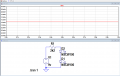
I have connected 10 LED's in parallels with switches (not shown in circuit diagram) and I want 1.44 mA of current flowing through any of the LED that I switch ON, but I have noticed that when I switch on 5 or more then 5 LED's then current them is reduced to from 1.44 mA to 1.2 mA (actual measurement from DMM).
I searched for the reason on internet and reason came because of resistance inherent in voltage source the voltage doesn't stay same in circuit.
Is there any solution to this problem.
Attachments
-
3.8 KB Views: 6
-
 86.3 KB Views: 11