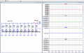
I have connected 10 LED's in parallels with switches on breadboard.

WBahn

Joined Mar 31, 2012
33,076
hi JC,
You are still missing the point of the TS's query/question.

Your posts #35 and #37 are not relevant to the TS's project.
With respect, you should address your input to directly helping the TS, rather than defaulting the posts from others, which have been based on the limited information the TS has provided.

Until he tells us otherwise, he is asking for an LED current of approx 1.4mA, which from the typical d/s value is possible, giving a Vfwd of approx 2.9/3.0 Volts.

E
But the TS is also asking for help creating a solution that results in a constant current of 1.44 mA +/- 0.09 mA. He appears fixated on using a voltage-source approach. The variability of Vfwd at that current is a significant issue in achieving that outcome.

I really wish the TS would describe what the purpose of this circuit is and what is important in the application, because I suspect he is either chasing a solution to a problem that doesn't exist, or that he thinks that his performance spec will solve a problem that it won't.

But, in the meantime, we are somewhat stuck discussing ways to achieve his stated requirements.
 

ericgibbs

Joined Jan 29, 2010
21,540
hi,
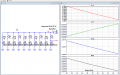
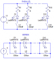
For a reference point only, this is what his LTS asc circuit simulation shows.

He has assumed the 9V battery source has a 50R output resistance.

I suspect he is using a PP3 9V battery, which has a higher output resistance than 50R
So as he adds more LEDs to the chain, the battery voltage falls, which results in a lower than ~1.4mA/LED.

The 2nd image shows the effect of Battery resistance.

E

EG 1317.pngEG 1318.png
 

Danko

Joined Nov 22, 2017
2,224
I measure current using ammeter by getting the probes in series between resistor and LED
purpose is to get constant current in all LED's 1.44 mA +/- 0.09mA
Connect LEDs in series and current of every diode will absolutely the same.
And more:
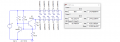
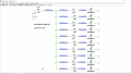
Use current source circuit and LEDs current will stable (1.44 mA with accuracy ±0.00213 mA or ±0.15%),
when voltage V1 changes from 30V to 60V.
1660306251700.png
1660305414991.png
 

Attachments

Last edited:

Audioguru again

Joined Oct 21, 2019
6,826
An old fashioned zener diode with transistor voltage regulator was in post #15 using a 4.7V/53mA zener diode with a transistor.
It was powered from a weak 9V battery and the regulation fails when the battery voltage drops a little.
I suggested using a 4.7V/5mA zener diode instead and maybe a Name Brand 9V alkaline battery.

Now I suggest using a low-dropout 5V regulator.
 

Tonyr1084

Joined Sep 24, 2015
9,744
Danko
I have connected 10 LED's in parallels with switches (not shown in circuit diagram) {BOLD ADDED BY TONYR1084} and I want 1.44 mA of current flowing through any of the LED that I switch ON, but I have noticed that when I switch on 5 or more then 5 LED's then current them is reduced to from 1.44 mA to 1.2 mA
The TS wants to be able to turn on a single LED, any one of 10 or as many as all 10 at once. Putting 10 LED's in series negates the desire to be able to switch certain LED's or a certain number of LED's on at any given desired moment.

Also, the TS wants to use low voltage. Your solution requires much higher voltages. From your image it appears you're suggesting >43V <44V. Such a supply would have to be built and would likely take up more space. The TS built his test on a 5V source and built that on a breadboard.

[edit] edited to correct mistakes and to add clarity to the TS original post and clarity to this post. [end edit]
 
Last edited:

ebeowulf17

Joined Aug 12, 2014
3,307
I used 50 ohm resistance in simulation for wires like these jumper wires
My power supply is this Breadboard power supply capable of delivering current <700 mA
I get it from above post that Breadboard can have loose connections which may induce resistance.
@Tejasvi471 I see that the breadboard power supply you're using offers regulated 5V and 3.3V outputs, and that it can be powered via USB or through a barrel jack with 6.5-12VDC.

Are you using USB to power the breadboard power supply module? If so you're probably not getting the regulated 5V you think you are. The voltage from the USB cord will be roughly 5V, but not necessarily very well regulated, and then your breadboard power supply is probably routing that 5V through a reverse protection diode and/or a voltage regulator IC (but any regulator IC can't actually regulate in this scenario because it needs the incoming voltage to be substantially higher than the desired output.)

This breadboard power supply module would probably work much better being fed from a 6.5-12V power supply than being fed from USB power. This might account for some of your difficulties.
 

WBahn

Joined Mar 31, 2012
33,076
He has assumed the 9V battery source has a 50R output resistance.

I suspect he is using a PP3 9V battery, which has a higher output resistance than 50R
So as he adds more LEDs to the chain, the battery voltage falls, which results in a lower than ~1.4mA/LED.
I didn't see anything that hinted that he was assuming, or using, a 9 V battery. If he was, then why are all of the circuits and simulations using a 5 V source?

In Post #14 he provided a link to the specific 5 V breadboard power supply that he is using.
 

ericgibbs

Joined Jan 29, 2010
21,540
Hi WB,
In Post #15 the TS, posted a circuit showing a change to a 9V supply, I took this as being a 9V battery.
So I modelled a basic CC circuit using for the simulation a 9V battery source, trying to show the TS the benefit of driving two series LEDs.

The TS’s did not challenge or correct this 9V battery assumption.

He then asked for a CV simulation, which I posted, again using a 9v battery.

Post #28., Post #44 also assumed a 9V battery.

Post #42, shows his original circuit, which did not meet his specification, using 5V supply.

I await, hopefully, that he will bring us all up to speed on the purpose of this project and the actual power source being used, so that we can finalize a circuit design

E
 

WBahn

Joined Mar 31, 2012
33,076
Ah, I see. I took that post (#15) as a "here's something I saw" aside that won't work for his goal of being able to arbitrarily switch on/off ten different LEDs.

I, too, wish he would tell us what he is trying to accomplish. I don't know why it is so hard to get posters to describe what they are trying to achieve so that we can help them figure out what they truly need instead of what they think they want.
 

Danko

Joined Nov 22, 2017
2,224
Putting 10 LED's in series negates the desire to be able to switch certain LED's or a certain number of LED's on at any given desired moment.
Really?
1660387034769.png
Also, the TS wants to use low voltage.
Do you know, exactly, what TS wants?
At least, TS told about equality currents of all LEDs
with high level of accuracy.
From your image it appears you're suggesting >43V <44V.
It is clear from image and from text that voltage of V1
may be from 30 V to 60 V. For example: 36 V or 48 V.
 
Last edited:

eetech00

Joined Jun 8, 2013
4,725
Hello,

I have connected 10 LED's in parallels with switches (not shown in circuit diagram) and I want 1.44 mA of current flowing through any of the LED that I switch ON, but I have noticed that when I switch on 5 or more then 5 LED's then current them is reduced to from 1.44 mA to 1.2 mA (actual measurement from DMM).
I searched for the reason on internet and reason came because of resistance inherent in voltage source the voltage doesn't stay same in circuit.
Is there any solution to this problem.
We can't help until you give us part numbers for the LED's and Switches so we can determine the voltage drops involved.
All this is required because of the tolerances you are working with.
We also need a schematic of your breadboard circuit.

Regarding the simulation...
You must specify the temperature (25C) in the simulation to match the Vf/If data on the datasheet. Otherwise, it 27C.
I ran an IV curve for the NSCW100 and measured Vf@1.44mA. I determined that Vf=2.8198V at If=1.44mA. So using these values calculated the required value for the limit resistor (1.014k), taking into account the 50 source resistance.

EDIT: Added limit resistor calculation

Resistor calculation (assume the LEDs are the same type):
Vsup=5V <---supply voltage
Rs=50 <---supply resistance
Vf=2.8198V <---LED Forward voltage drop
If=0.00144A <---LED Forward current (1.44mA)
nLed=10 <---Number of LEDs

VRs=(If x nLed) x Rs=0.72v <---Rs voltage drop

Rlimit=((Vsup-VRs)-Vf) / If = 1.014k ohms <---limit Resistor value (or next larger standard size)

See below:

1660409615028.png
 
Last edited:

Audioguru again

Joined Oct 21, 2019
6,826
Simulations show dreams that everything is perfect. The model for the LED will have only "typical" values but when you buy the LEDs they might all be different with some having minimum specs and others having maximum specs.
In real life you might need to buy hundreds of the LED to find a few with specs that match perfectly.
 

Jon Chandler

Joined Jun 12, 2008
1,631
Simulations show dreams that everything is perfect. The model for the LED will have only "typical" values but when you buy the LEDs they might all be different with some having minimum specs and others having maximum specs.
In real life you might need to buy hundreds of the LED to find a few with specs that match perfectly.
This has been explained many times, but still the "typical" Vf vs current graph is taken as the exact value for every LED under every condition.
 

ericgibbs

Joined Jan 29, 2010
21,540
Simulations show dreams that everything is perfect
Only to engineers who don't know how to interpret the results.

In real life you might need to buy hundreds of the LED to find a few with specs that match perfectly.
A well-designed circuit does not require that all the LED's have to be matched perfectly.
 

eetech00

Joined Jun 8, 2013
4,725
Simulations show dreams that everything is perfect. The model for the LED will have only "typical" values but when you buy the LEDs they might all be different with some having minimum specs and others having maximum specs.
In real life you might need to buy hundreds of the LED to find a few with specs that match perfectly.
Yes....it is not a HW breadboard...it is a simulation. But manufacturing variances could be included if I wanted to include them.
 

WBahn

Joined Mar 31, 2012
33,076
Simulations show dreams that everything is perfect.
Yes and no. That all depends on the simulation models. Some are simplistic, and others are extremely accurate. When I was designing an IC on the IBM 130 nm process the model for each transistor was a subcircuit with over 300 components in it!

When I tested the first IC that came back after I started working as an IC designer (so it was a chip designed and fabbed before I started), I expected the chip to behave only in rough comparison to the simulations. I was surprised that every single on-chip bias voltage that was generated for the internal current mirrors was within a couple millivolts of the simulation results (and within the tolerance of the meters we were using).

Great lengths go into the simulation models for IC processes because you can't breadboard the circuit before fab -- you have no choice but to rely on the simulation results. With mask sets costing millions of dollars, you can bet that companies expect, demand, and are willing to pay for, simulation models that are damn good and that take into account just as many parameters as they can characterize, including both run-to-run process variations and on-chip transistor-to-transistor matching.
 

Audioguru again

Joined Oct 21, 2019
6,826
I have a cheap Chinese flashlight (torch) that has 60 LEDs connected all in parallel. I did not disconnect any of them to measure them but they appear to be matched very well.
 

WBahn

Joined Mar 31, 2012
33,076
I have a cheap Chinese flashlight (torch) that has 60 LEDs connected all in parallel. I did not disconnect any of them to measure them but they appear to be matched very well.
Such binning is possible in mass production. If you buy enough LEDs from the manufacturer, you can pay them to bin the parts. What it then comes down to is whether the cost per unit to get binned parts is less than the cost per unit of doing the circuit right to work with unbinned parts. But binning the parts only matches them today. It does not guarantee that they will stay matched as they age. Plus, the company likely on cares about binning them close enough so that they appear matched to the buyer when they turn it on the first time. Given the relatively poor sensitivity to illuminance of the human eye, that actually doesn't require all that much.

I have a number of cheap Chinese flashlights that looked fine when I first bought them, but now when I turn them on many of the LEDs are putting out almost no light at all because they are no longer matched due to aging effects.
 

Tonyr1084

Joined Sep 24, 2015
9,744
Danko Just for a moment, assume S1 (the parallel switch to D1) is the only LED he wants switched off. When you bypass D1 with S1 you change the circuit characteristics and increase the current through the rest of the LED's. Now for a moment assume he only wants D10 lit (S10 would be open). Without the 9 other voltage drops across those LED's the voltage through D10 and the associated current would be nearly a dead short to the power supply and would burn D10 out faster than you could blink.

I respect your opinions and views but I disagree with your approach. Particularly because the TS stated he might want to have all LED's out but one. I can assume there would be a circumstance where he wanted ALL the LED's off but the power supply still powered. That would be a dead short. Or at least through the one current limiting resistor (not shown in your diagram but assumed to be there) ALL the current would be going through that resistor and would get very hot if it was sufficient in size (wattage) to not burn out. But such a high wattage could potentially start a fire. This is why I disagree with your approach.

With the TS approach, each LED has its own resistor. So regardless of what state the others are in, the one that may be under consideration would be operating at the proper current. However, it occurs to me that perhaps you have a resistor at each LED and use the switch to either drop out both the resistor AND LED or just the LED only. In which case I see so many potential changes to current flow that I can't predict how the circuit would function. I suspect it would fail if the right set of switches were active/inactive. I could model it but I don't have that much time. I will model three LED's set up the way you suggest and see what numbers I come up with.
 

Tonyr1084

Joined Sep 24, 2015
9,744
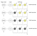
Admittedly I'm not 100% confident in my numbers but this is what I got using four examples of ONLY THREE LED's in series with a parallel shunt switch: (below) Each LED ON is represented by yellow coloring and the black coloring represents an LED that has been bypassed by its parallel shunt switch. With ALL LED's bypassed your CC regulator is pumping out 22.5mW with all LED's OFF. Can your CC regulator handle that much heat?
1660495764310.png
 
Top