 Facebook
 Google
 GitHub
 Linkedin
Is not current determined by voltage and resistance passively?
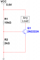
e.g. How can the gain factor be determined collectively because the current between the collector and emitter varies depending on the resistance of the load at below circuit?
e.g. How can the gain factor be determined collectively because the current between the collector and emitter varies depending on the resistance of the load at below circuit?
Attachments
-
 10 KB Views: 22


