I can't program my pic16f627a with pickit3

Thread Starter

Arjune

Joined Jan 6, 2018
354
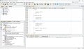
I am using the mp lab x ide and the mp lab x ipe with the pickit 3 to program my pic16f627a to blink an led. I include two screenshots programming with the IDE since the IPE failed also.
I am powering the chip (target device) with a 5 volt power supply. I am concerned with the expected and received hex code at the end which I don't have knowledge of hexadecimal. I tried with a header file and without a header file. I am using mp lab x ide v6.2.0 and the ipe is also v6.2.0. I bought a second pickit3 on amazon (the first one was on ebay) and that didn't work either tonight. Maybe the code is incomplete (I copied it from the web)? I tried a second pic16f627a and that failed also.

pickit3-1- 2025-11-28 18-54-20.pngpickit3-2- 2025-11-28 18-53-25.png
 

Thread Starter

Arjune

Joined Jan 6, 2018
354
I added the (CMON=7;) line to the program but still programming fails. I also get the error "cannot program a production build to debug header" when using the IDE to program the target device and I am using a debug header in the properties of the IDE. I also get a "connection failed" when attempting to program with the IDE with the debug header removed from properties (AC162053).-I think external power to the target device is somehow not active when programming with the IDE. Also, I get the same hex error when programming with the IPE.

I don't know but for some reason I was able to program the target device (pic16f627a) successfully with the IPE. The LED is blinking and pin 4 i(mclr) s connected to positive with a 10k resistor after programming. The LED is connected to pin 9 (RB3) to ground via a 1k resistor to limit current to the LED.

I am going to try to repeat the programming process...to see if I succeed again. The key element was the CMCON=7; line.

pickit3 using IPE-2 2025-11-29 15-29-00.png
 

BobTPH

Joined Jun 5, 2013
11,466
Create a new project in the IDE for the pic16f627a. Build it and program it. Hopefully this works.

Assuming it worked, now paste in the code for your program and build and program it again.
 

Thread Starter

Arjune

Joined Jan 6, 2018
354
I can't program the device again with the same project using the IPE- I get the same hex error: What build do I click on in the IDE? pickit3-verify2025-12-01 09-52-41.pngpikit3 wiring to pic16f627a.png
 

AlbertHall

Joined Jun 4, 2014
12,619
Where the error occurs, 0x2007, is the config memory. I am not familiar with IPE. I use MPLABX for all my programming soI don't know why this error is occuring.
 

trebla

Joined Jun 29, 2019
599
Do you use the AC162053 or the actual PIC16f627 chip? Debug header and the production MCU have different memory organisation.
 

Thread Starter

Arjune

Joined Jan 6, 2018
354
Do you use the AC162053 or the actual PIC16f627 chip? Debug header and the production MCU have different memory organisation.
I am thinking that the debug header is instructions for programming the chip. I am actually using the chip. I suspect the theory of GOD is causing my confusion with electronic theory. I was never able to learn the electronic musical keyboard for my rap. Is the space of data being exchanged with another for confusion? My space is not being apprehended for recognition?
 

AlbertHall

Joined Jun 4, 2014
12,619
I am thinking that the debug header is instructions for programming the chip.
The debug header contains the instructions for the debugging process. May PIC chips have this code built in and so do need a debug header however the '627 does not and so needs the debug header to be able to step through a program and view values of variables during execution and so on.
 

trebla

Joined Jun 29, 2019
599
I suspect the theory of GOD is causing my confusion with electronic theory.
This is not about electronic theory nor personal qualities, it's about reading datasheets :)
In section 14.13 "In-Circuit Debugger" from PIC16F627A latest datasheet (DS40044G) is explanation why the manufacturer is decided to use different modification of this MCU chip for hardware debugging.
 

Thread Starter

Arjune

Joined Jan 6, 2018
354
This is not about electronic theory nor personal qualities, it's about reading datasheets :)
In section 14.13 "In-Circuit Debugger" from PIC16F627A latest datasheet (DS40044G) is explanation why the manufacturer is decided to use different modification of this MCU chip for hardware debugging.
Don't forget human nature. We're alien to each other.
 

Thread Starter

Arjune

Joined Jan 6, 2018
354
I guess I have to give up. I don't think the truth can be relied upon. The microcontroller may be designed incorrectly with the assignment of more than one function per pin making it confusing for IT (the spirit) to make a decision as to what function to assign to a pin. For instance, making the "memory clear (pin 4)" pin high after programming. The operation intelligence is forcing IT to be logical instead of to wonder about what to do. This is the problem with education in America--saying only one way is correct.
 

nsaspook

Joined Aug 27, 2009
16,254
For these types of things, only one way is correct, but there a plenty of wrong ways and I've done most of them over the years.
 

Thread Starter

Arjune

Joined Jan 6, 2018
354
It is how I start every project.
I did the new project but it failed to program device using the IPE. On the IDE it was saying there was a configuration error and the make file could not be created. But I think it was referring to the wrong project. I lost that configuration error tab -near the output tab, on the bottom of the screen to the right because I X it out by accident. I don't know what type of configuration that is. Please explain. Also, please explain the settings of the IDE to how I route my external 5v power to the Pickit3-target device. How do I make sure I'm seeing the right windows for my current project also?

Do I hold in reset or release from reset.

I suspect the C program is wrong---aren't there banks of the device I have to consider programming?
 
Last edited:

Thread Starter

Arjune

Joined Jan 6, 2018
354
If you program in 'C' then the compiler will take care of the banking. If you use assembler then you do need to take care of banking.
Al, Can you show me how to apply assembly language to blink the LED and use the pickit3 and create a new project as such please? I want to try assembly language and flash the same microcontroller with it. I don't know assembly language, for that matter, even C language so I need examples. Also I need to know how to restore the configuration tab on the bottom of the IDE next to the output tab to show configuration errors. What type of configuration is the message there referring to?
 

AlbertHall

Joined Jun 4, 2014
12,619
Al, Can you show me how to apply assembly language to blink the LED and use the pickit3 and create a new project as such please? I want to try assembly language and flash the same microcontroller with it. I don't know assembly language, for that matter, even C language so I need examples. Also I need to know how to restore the configuration tab on the bottom of the IDE next to the output tab to show configuration errors. What type of configuration is the message there referring to?
I find assembler much harder than C so I use C exclusively.
I have attached an image of my MPLABX screen. Do you mean the 'Output - Configuration Loading Error' tab that is missing?
If so that appears when first loading MPLABX.
 

Attachments

Top