I burned my PIC (with I guess my potentiometer)

Thread Starter

KansaiRobot

Joined Jan 15, 2010
324
Well, there is always a first for everything and today I burned my PIC. (smoke coming out of it):confused:
The connection was very simple nothing complicated and the thing is I had use this connection before without problems and without burning it. This time instead of batteries I used a AC-DC conversor and so I thought that may be why...

But then one of the staff told me that my potentiometer circuit was badly designed, and yes I think it was.

The story started some years ago. I was using this pot:
http://www.dst-gmbh.de/sensors/rdc40kat.pdf

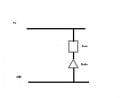
Now if you see in the last page there is a circuit so I built the following:


On that time it worked well. Later on I started using a different Pot
http://www.linkman.jp/data/02.R1610N-_B1.pdf
with the same circuit.
I didnt notice though that the first pot had a Contact Resistance R1 "set to a high level because its output terminal is designed to directly connect to the A/D port of the microprocessor"

Strangely it worked well, I even move the pot from min to max and never saw smoke coming out of the PIC.

Until this afternoon... it happened that this morning I left the potentiometer in the position closest to 5V. And later I just connected the 5V with that.

The staff told me that in that position there is no resistance so a lot of current entered and burned the PIC

he also said that the A/D module needs time to initialize.
he also talked that the capacitor was not necessary and even said I shouldnt use it but later contradicted himself. he talked about "latch up".
He also said that modern microprocessors dont accept that kind of circuit.

Anyway, I guess I should have put a resistor "R1" from 1K to 10K to limit the current that entered the PIC.

Guess it is a leason learned.. but wonder why it didnt burned before, and I have used the circuit tens of times... (always with batteries though)

Any comment and advice appreciated
 
Last edited:

ScottWang

Joined Aug 23, 2012
7,500
What voltage of that Vcc?
What's the pic number?
What voltage provided for Vdd of pic, 3.3V,5V?
What's the pot that you used for?
 

Thread Starter

KansaiRobot

Joined Jan 15, 2010
324
What voltage of that Vcc?
What's the pic number?
What voltage provided for Vdd of pic, 3.3V,5V?
What's the pot that you used for?
1) Vcc was 5V (actually I think 5.3V)
Before I had tried the circuit with four batteries (1.5x4) so 6V and there were no problems.
Now I used a AC-DC power supply  COSEL
https://www.cosel.co.jp/en/products/pdf/SFE_LCC.pdf
(I think-I am on a train so can't see my data right now)

2) PIC18F2550

3) 5V

4) I used
http://www.linkman.jp/data/02.R1610N-_B1.pdf

It seems that I needed a contact resistor to limit the current because if the Pot wiper was close to the 5V extreme there is nothing limiting the current that enters the AD converter (pin 2) of the PIC
 

OBW0549

Joined Mar 2, 2015
3,566
It seems that I needed a contact resistor to limit the current because if the Pot wiper was close to the 5V extreme there is nothing limiting the current that enters the AD converter (pin 2) of the PIC
Provided the pot is supplied from the PIC's Vdd supply (or a voltage lower than that), you shouldn't need any resistance in series with the A/D input to limit current; if the pot is supplied by some voltage higher than Vdd, then obviously you do.

It takes a LOT of current to make PICs emit their Magic Smoke, and I suspect nsaspook is right: check your power supply polarity before plugging in another PIC.
 

ScottWang

Joined Aug 23, 2012
7,500
Vdd for Pic18F2550 is 2.0V to 5.5V, probably it was damaged by the 1.6V*4 = 6.4V battery, new battery is 1.6V not 1.5V, I don't think a power could provide 5V/3A will kill the chip which can accept up to 5.5V, or reversed the voltage for pic.

You may need to limited the analog input voltage as in parallel with a 5.1V zener.
 

OBW0549

Joined Mar 2, 2015
3,566
Sorry but I do not understand.

Where "Out" goes to? To the Vcc pin in the PIC?
Of course not; it goes to the PIC A/D input pin, as you described.

I don't believe there is anything at all wrong with your pot or how you are connecting it, nor do I believe the pot has anything whatsoever to do with your PIC burning up.

Most likely, the PIC is being destroyed by one of two things:

1) Your power supply might be connected with the wrong polarity; or
2) The power supply might be "glitching" when it is first turned on, with the output voltage briefly going very high before settling back down to 5 volts. This could destroy the PIC.

Always, ALWAYS, when using any kind of switching power supply, first check its output with an oscilloscope to make sure it doesn't do evil things at turn-on or turn-off.
 

Kermit2

Joined Feb 5, 2010
4,162
a diode and small fuse on the power input Vcc to provide polarity protection would be good as well. backward battery connection would conduct through diode and fuse would blow.
+1 on the 5.1 zener as well. I was instructed to always protect A-D inputs even when they don't seem to need it.
 

atferrari

Joined Jan 6, 2004
5,011
Of course not;
My bad. Thanks.

BTW, not used a switching PSU yet but I never considered checking what it does at startup. Will keep that in mind.

I recall a PSU where the output was not connected to the load when switched on. The user had to push a button to actually apply / cut power to the circuit. Maybe because of this?
 

ErnieM

Joined Apr 24, 2011
8,415
My bottom line is there is nothing in your schematic or parts that would lead to such a catastrophic failure, even if only the Pot was powered. Either some element you did not show had a problem or the power was connected backwards.

I recommend NOT using a battery when experimenting as any battery can deliver a large uncontrolled current sufficient to destroy devices with lots of smoke. A lab supply or even a simple 3 terminal voltage regulator will have built in current limiting and make things much safer.

>>I didnt notice though that the first pot had a Contact Resistance R1 "set to a high level because its output terminal is designed to directly connect to the A/D port of the microprocessor"

Well, what they mean is the loading of the circuit reading this resistor should be 1M or greater. A PIC wants between 1K and 10K (depends on which specific PIC) maximum source resistance to get an accurate reading. However, no damage should result from either having or not having this resistance. (I do recommend putting some resistance there in case the voltage being sensed rises above the Vdd of the PIC.)


>>Until this afternoon... it happened that this morning I left the potentiometer in the position closest to 5V. And later I just connected the 5V with that.

>>The staff told me that in that position there is no resistance so a lot of current entered and burned the PIC

With everything else being correct the only current that enters the PIC this way is the same current the PIC needs to run: the PIC will power itself thru the input pin via the ESD diode there; check the spec for your PIC for the PORT pin schematic to see this.

>>he also said that the A/D module needs time to initialize.

True dat, but the pin will initialize at power up (instant) as an analog pin so no damage from this will ever result.

>>he also talked that the capacitor was not necessary and even said I shouldnt use it but later contradicted himself. he talked about "latch up".

The external cap is good as a filter for noise. I have never seen “latch up” in a PIC.

>>He also said that modern microprocessors dont accept that kind of circuit.
Just wrong period.

>>Anyway, I guess I should have put a resistor "R1" from 1K to 10K to limit the current that entered the PIC.

As I said above the exact value depends on the PIC: tell me the part number and I will show you where this is in the spec sheet. It is a good practice but not essential.
 

Thread Starter

KansaiRobot

Joined Jan 15, 2010
324
Thank you for all the answers

Provided the pot is supplied from the PIC's Vdd supply (or a voltage lower than that), you shouldn't need any resistance in series with the A/D input to limit current; if the pot is supplied by some voltage higher than Vdd, then obviously you do.

It takes a LOT of current to make PICs emit their Magic Smoke, and I suspect nsaspook is right: check your power supply polarity before plugging in another PIC.
What would happen if I connect a pin of the PIC to 5V with a jumper cable??
specially what would happen if I connect that pin to a 5V/3A source?


Vdd for Pic18F2550 is 2.0V to 5.5V, probably it was damaged by the 1.6V*4 = 6.4V battery, new battery is 1.6V not 1.5V, I don't think a power could provide 5V/3A will kill the chip which can accept up to 5.5V, or reversed the voltage for pic.

You may need to limited the analog input voltage as in parallel with a 5.1V zener.
I have used the batteries tens of times and never burned anything. It was when I connected the AD-DC power supply that smoke came out

Of course not; it goes to the PIC A/D input pin, as you described.

I don't believe there is anything at all wrong with your pot or how you are connecting it, nor do I believe the pot has anything whatsoever to do with your PIC burning up.

Most likely, the PIC is being destroyed by one of two things:

1) Your power supply might be connected with the wrong polarity; or
2) The power supply might be "glitching" when it is first turned on, with the output voltage briefly going very high before settling back down to 5 volts. This could destroy the PIC.

Always, ALWAYS, when using any kind of switching power supply, first check its output with an oscilloscope to make sure it doesn't do evil things at turn-on or turn-off.
I know it sounds a stupid question, but how can I check the polarity? Since a multimeter checks voltage by putting it in paralel to a circuit I am guessing building a circuit with only one resistor and then measuring the voltage across this register... ??
 

Thread Starter

KansaiRobot

Joined Jan 15, 2010
324
a diode and small fuse on the power input Vcc to provide polarity protection would be good as well. backward battery connection would conduct through diode and fuse would blow.
+1 on the 5.1 zener as well. I was instructed to always protect A-D inputs even when they don't seem to need it.
any schematic that could be provided would be very useful :)

My bottom line is there is nothing in your schematic or parts that would lead to such a catastrophic failure, even if only the Pot was powered. Either some element you did not show had a problem or the power was connected backwards.

I recommend NOT using a battery when experimenting as any battery can deliver a large uncontrolled current sufficient to destroy devices with lots of smoke. A lab supply or even a simple 3 terminal voltage regulator will have built in current limiting and make things much safer.

>>I didnt notice though that the first pot had a Contact Resistance R1 "set to a high level because its output terminal is designed to directly connect to the A/D port of the microprocessor"

Well, what they mean is the loading of the circuit reading this resistor should be 1M or greater. A PIC wants between 1K and 10K (depends on which specific PIC) maximum source resistance to get an accurate reading. However, no damage should result from either having or not having this resistance. (I do recommend putting some resistance there in case the voltage being sensed rises above the Vdd of the PIC.)


>>Until this afternoon... it happened that this morning I left the potentiometer in the position closest to 5V. And later I just connected the 5V with that.

>>The staff told me that in that position there is no resistance so a lot of current entered and burned the PIC

With everything else being correct the only current that enters the PIC this way is the same current the PIC needs to run: the PIC will power itself thru the input pin via the ESD diode there; check the spec for your PIC for the PORT pin schematic to see this.
what happens if I connect a 5V/2A directly to a pin of the PIC?

>>he also said that the A/D module needs time to initialize.

True dat, but the pin will initialize at power up (instant) as an analog pin so no damage from this will ever result.

>>he also talked that the capacitor was not necessary and even said I shouldnt use it but later contradicted himself. he talked about "latch up".

The external cap is good as a filter for noise. I have never seen “latch up” in a PIC.

>>He also said that modern microprocessors dont accept that kind of circuit.
Just wrong period.

>>Anyway, I guess I should have put a resistor "R1" from 1K to 10K to limit the current that entered the PIC.

As I said above the exact value depends on the PIC: tell me the part number and I will show you where this is in the spec sheet. It is a good practice but not essential.
I am using a PIC18F2550. Also I am considering a PIC18F2553
 

OBW0549

Joined Mar 2, 2015
3,566
What would happen if I connect a pin of the PIC to 5V with a jumper cable??
specially what would happen if I connect that pin to a 5V/3A source?
Assuming the PIC itself is powered from that same 5V, and the PIC pin is configured as a digital input or analog input, nothing. If the PIC pin is configured as an output, and the pin's output latch bit is set to "0", then the PIC might get a little warm since the output would be fighting the 5V you are applying to that pin.

I know it sounds a stupid question, but how can I check the polarity? Since a multimeter checks voltage by putting it in paralel to a circuit I am guessing building a circuit with only one resistor and then measuring the voltage across this register... ??
Why do you even need a resistor? Just connect the voltmeter to the power supply and read the voltage...
 

nsaspook

Joined Aug 27, 2009
16,298
Thank you for all the answers
I have used the batteries tens of times and never burned anything. It was when I connected the AD-DC power supply that smoke came out
The max voltage spec of that PIC is very conservative (old process) so I don't think a little over-volt will kill the chip and let the magic 'soul' smoke out that's made from the very best snake oil. The prime suspects are reversed power or a high energy transient coupled to/from the power supply like a static discharge when the circuit is connected.

Both can kill but high energy transients can really make a mess if it causes a low resistance short on the die.
 

alfacliff

Joined Dec 13, 2013
2,458
like a lot of pic chips, your ad pin is probably used as an i/o pin when the ad is not in use. thats the reason the guy said the ad pin takes a little time to initialize. if the 5 volt supply was connected to the ad pin when the power was turned on, and the pin was not initialized as an ad pin, it might have smoked the chip.
 

Kermit2

Joined Feb 5, 2010
4,162
no schematic is required. put a diode across the Vcc pin and ground oriented to be reverse biased in normal operation. Add an inline, fastblow fuse to the incoming power. If power polarity is accidentally reversed, the diode becomes forward biased and conducts straight into the ground connection, immediately after, the fuse blows to prevent overcurrent damage to the circuit board around the power entry point.
 

ScottWang

Joined Aug 23, 2012
7,500
Ω
I have used the batteries tens of times and never burned anything. It was when I connected the AD-DC power supply that smoke came out
You could using 9V or 12V power and adding a 78L05 or 78M05, it will depending the current of uC, or using 5V power and adding the protection circuit as following.


ErnieM

Joined Apr 24, 2011
8,415
what happens if I connect a 5V/2A directly to a pin of the PIC?
Most times, absolutely nothing.

Worst case, when the pin is an output set output a low: the pin gets damaged, either the transistor opens or the internal wirebond fuses open.

But no smoke, and just this one pin gets damaged. The rest of the chip tends to keep on working just fine.

Most of us old timers have a few PICs like that in our scrap box. ;)
 

Thread Starter

KansaiRobot

Joined Jan 15, 2010
324
no schematic is required. put a diode across the Vcc pin and ground oriented to be reverse biased in normal operation. Add an inline, fastblow fuse to the incoming power. If power polarity is accidentally reversed, the diode becomes forward biased and conducts straight into the ground connection, immediately after, the fuse blows to prevent overcurrent damage to the circuit board around the power entry point.
I am sorry but without schematics I understand almost nothing :(
so what you are saying is something like this?
diode.jpg
 
Top