I bias, RC and RB on Transistor Exercise

Thread Starter

Marco Sarubbi

Joined Aug 22, 2018
2


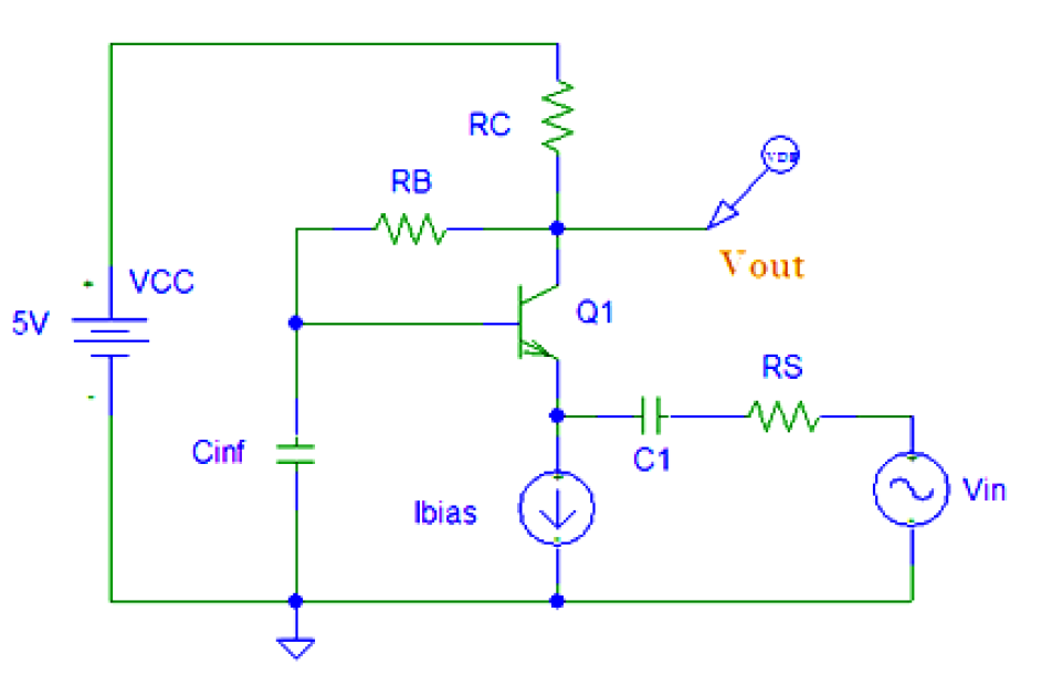
So i have this circuit and i need to find Ibias so that the emitter impendence will be equal to RS. I also need to find RC and RB knowing that Vce = Vcc/2 and Ve = 0.5 V.
What i know is Vcc = 5 V, C1 = 1.6 uF, RS = 20 ohm, Vbe = 0.65 V and β = 50
I'm a bit stuck, any help from you guys would be really appreciated, thank you very much
 

Attachments

danadak

Joined Mar 10, 2018
4,057
Always start by writing down what you know because that will
lead you to a series of calculations, and then answers.

Look at the hybrid pi model and its describing equations.

So you know what Rs is, therefore you know what Re is in the model,
this tells you gm needed, that leads to calculating collector current......

Regards, Dana.
 

Thread Starter

Marco Sarubbi

Joined Aug 22, 2018
2
Always start by writing down what you know because that will
lead you to a series of calculations, and then answers.

Look at the hybrid pi model and its describing equations.

So you know what Rs is, therefore you know what Re is in the model,
this tells you gm needed, that leads to calculating collector current......

Regards, Dana.
Thank you for the answer, one thing jumped in my mind, is it correct to consider the circuit as a collector feedback bias?
 

Jony130

Joined Feb 17, 2009
5,598
What you need to do first is to find the emitter impedance for a common base amplifier.
Do you know how to calculate it? And base on this information are you able to find the desired collector current?
Do you ever hear about re = Vt/Ie?
 
Last edited:

MrAl

Joined Jun 17, 2014
13,728


So i have this circuit and i need to find Ibias so that the emitter impendence will be equal to RS. I also need to find RC and RB knowing that Vce = Vcc/2 and Ve = 0.5 V.
What i know is Vcc = 5 V, C1 = 1.6 uF, RS = 20 ohm, Vbe = 0.65 V and β = 50
I'm a bit stuck, any help from you guys would be really appreciated, thank you very much
Hi,

Here are some tips...

Step 1, replace the transistor with a current controlled current source with gain equal to Beta.
Step 2, consider the capacitor C1 an open circuit for DC.
Step 3, once you find the bias point you can then replace Cinf with a voltage source, assuming that is a very very large value capacitor.

You then can proceed to analyze this just like any other circuit where you need to know voltages, currents, powers, or impedances.

See if you can get going by doing step 1 above first and considering C1 as an open circuit and then try to find your required bias point voltage.

One thing though, i dont see any mention of what the gain of the stage should be. Maybe that is implied though the other specs but i have not done this circuit yet either.

[LATER]
Took a closer look at this circuit. It appears that RC is somewhat simple to calculate knowing the other facts about this circuit like for example Ve and R3. Look at what the circuit becomes when you get rid of Cinf and C1 in order to find the DC bias point.
 
Last edited:

MrAl

Joined Jun 17, 2014
13,728
Hello again,

A conflict came up while looking at this circuit in more detail. This involves the Cinf capacitor.

If we want to set a given impedance at the emitter (which is the input for this circuit) then we cant simultaneously set Cinf to a very very large value cap (for AC analysis) because the assumed base emitter voltage is constant (0.65v). That means the input impedance would be zero.
This means they must have overlooked something or else we just dont set Cinf to a large value and in fact just take it out of the circuit.

If we were doing a full blown analysis we would have some base and emitter internal resistance and that would partly help here, but for one we are not given any such specs and two even if we were that would probably dominate the input impedance and that does not seem like it should be part of this problem based on the first post in this thread.

What this means is that we need more information or else we just have to assume that Cinf doesnt do anything even for AC. That then allows the freedom to set the input impedance as requested in the first post.

To be clear, we can still find the DC bias point though so that's still a good exercise. If we eliminate Cinf then we can set the input impedance too. So the conflict only appears when we go to do the AC analysis.
 
Last edited:
Top