I am confused on using MOSFETS in a voltage doubler circuit

Thread Starter

Wasswa

Joined Feb 23, 2021
9
Thank you so much
Danko

shortbus


The Voltage source is a Piezoelectric energy harvester or sensor generating low frequencies. Its supplying 200mV to 400mV with low power about 50mW to 100mW.
MisterBill2
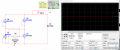
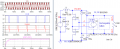
The Four NMOS rectifier circuit is another approach I have been reviewing to solving the rectifying problem from this paper for this low supply in millivolts also highlighted by you MisterBill2. I am experiencing a low output voltage even with a smoothening capacitor in multisim assuming 200mV is considered. Can anyone share some insights or a working schematic specifically on this 4NR circuit diagram approach please?
Or the the 4NR + DC CD converter + a voltage regulator to complete the entire AC DC converter schematic circuit for low voltage energy harvester like a piezo-sensor


1615219626107.png

1615218917564.png
 

Attachments

Last edited:

Danko

Joined Nov 22, 2017
2,219
Can anyone share some insights or a working schematic specifically on this 4NR circuit diagram approach please?
I believe 4NR circuit will work very well with transistors which have threshold voltage about 1 mV
and Rds(ON) in few mΩ.
The Voltage source is a Piezoelectric energy harvester or sensor generating low frequencies.
Piezoelectric source usually has big voltage - volts or even kilovolts (10 kV in lighter's piezoelement)
but very small current - microamps.
Its supplying 200mV to 400mV with low power about 50mW to 100mW.
Load current @200 mV and 50 mW is 0.25A, so electrodynamic source can provide such big current.
Resistance of load is 200mV / 0.25A = 0.8 Ω.
For maximal efficiency series resistance of source's coil should be equal 0.8 Ω too.
Then minimal idle (without load) source voltage is 0.25A * (0.8 Ω + 0.8 Ω) = 400mV.
So, idle source voltage range is from 400 mV to 800 mV, load voltage changes from 200mV to 400 mV
and power in load from 50 mW to 200 mW (not to 100 mW).

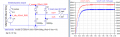
Converter on picture below consumes 48.4 mW from electrodynamic source V1 and converts
200 mV AC to 6,53V DC @ 1kΩ load with efficiency 88%.
1615377318533.png
===========================================================================================================
ADDED:
Your case:
1615512454163.png
 

Attachments

Last edited:

MisterBill2

Joined Jan 23, 2018
27,998
I am thinking that I recall something about the goal being to put it all inside a small value, such as a key fob. So it is going to be interesting to see the election of parts that will fit somehow. Making small packages is a challenge for serious engineers with experience and resources. For others the challenge may be even greater.
 

Thread Starter

Wasswa

Joined Feb 23, 2021
9
I believe 4NR circuit will work very well with transistors which have threshold voltage about 1 mV
and Rds(ON) in few mΩ.

Piezoelectric source usually has big voltage - volts or even kilovolts (10 kV in lighter's piezoelement)
but very small current - microamps.

Load current @200 mV and 50 mW is 0.25A, so electrodynamic source can provide such big current.
Resistance of load is 200mV / 0.25A = 0.8 Ω.
For maximal efficiency series resistance of source's coil should be equal 0.8 Ω too.
Then minimal idle (without load) source voltage is 0.25A * (0.8 Ω + 0.8 Ω) = 400mV.
So, idle source voltage range is from 400 mV to 800 mV, load voltage changes from 200mV to 400 mV
and power in load from 50 mW to 200 mW (not to 100 mW).

Converter on picture below consumes 48.4 mW from electrodynamic source V1 and converts
200 mV AC to 6,53V DC @ 1kΩ load with efficiency 88%.
View attachment 232393
===========================================================================================================
ADDED:
Your case:
View attachment 232519
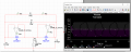
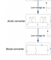
Once again this active voltage doubling AC/DC converter is one of the approaches I looked at. So far the circuit again captures the input negative and positive cycles of 200mv alternating input voltage to doubled output at the 100-ohm load. AC input supplying once again ranges from 200mV at min to 400mV at maximum with low power about 50mW to 100mW. I want to add on a boost converter. I want to boost these 2x output voltages at the 100-ohm load to obtain a signal usable DC output forexample 5volts that charges a rechargeable battery. I appreciate the insights Mr Danko and the entire experts in general.
1616016561448.png
1616016944501.png
 

Attachments

MisterBill2

Joined Jan 23, 2018
27,998
How wil those opamps or comparators be powered?? And charging a 5 volt battery from a 0.400 volt source is going to need quite a special circuit. One more thing is that you can not get more power out than you put in.
 

Thread Starter

Wasswa

Joined Feb 23, 2021
9
How wil those opamps or comparators be powered?? And charging a 5 volt battery from a 0.400 volt source is going to need quite a special circuit. One more thing is that you can not get more power out than you put in.
It is possible to charge the battery to around 3.5v or 5v if the double 0.400v is boosted with a boost converter first before it outputs to the rechargeable battery.
The op- amp can be powered by an initially charged rechargeable battery. Also if output from the voltage doubler circuit have provided is made high enough by boosting the 2x outputs with a booster converter some of it can charge the rechargeable battery well as the other fed-back to operate the comparators. One of the 2 papers, I have attached explains it much clearer please have a look at them MisterBill2 but for now I need help with circuit adding on the boost converter or a battery storing the 2 outputs as DC
 

Attachments

Last edited:

MisterBill2

Joined Jan 23, 2018
27,998
The scale on the one plot is in microwatts, which is not much power at all.
In addition you have mentioned charging a battery to 5 volts. And it is still not clear about the current capability of that piezo-electric source that pproduces millivolts of output. And making this challenge more interesting, it needs to be small enough to fit in a key case, which I am guessing is part of a key, perhaps half a cm thick and possibly as large as 2 cm by 2 cm. THAT will need a level of fabrication skill far beyond the capabilities of most folks.

And still, we have no description of the actual application, aside from charging some battery of some unknown capacity, to 5 volts.
How will the TS assemble this system if the perfect design is created and the right components are determined??
 
Top