HVAC Issue with Relays

killivolt

Joined Jan 10, 2010
836
Same effect either side of Fan, reduced current due to unloaded fan.
Max.
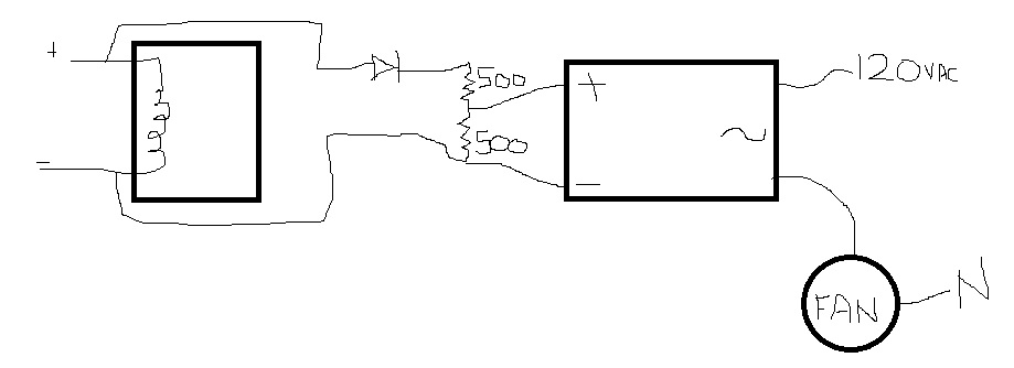
When it comes to motors your the one to help him; I only have some field experience. At this point I think he needs to call someone who has a hydrostatic pressure gauge.

kv

Edit: Thats provided the system was designed properly.
 

tcmtech

Joined Nov 4, 2013
2,867
Looks like you have ran into the common problem associated with far too many HVAC systems. They are over priced, under built and designed by idiots. :mad:

My first suggestion would be to replace all power carrying wiring with a minimum o f 12 ga and build up any power carrying circuit board traces with a wire overlay or point to point soldered in jumpers as well. After that I would replace any undersized relays or switches with a good 20 -30 amp rated devices.

Last I would move it up to a 20 amp fuse or circuit breaker which is what any device that takes 14 - 15 amps running current should have per most common codes.
 

Thread Starter

DC_Kid

Joined Feb 25, 2008
1,242
the system ducting has not changed, and there are no obstructions in any of the ducting.

post #22, thats exactly what i had done (less the additional relays, and its already on a 20A breaker fed via 10/2 romex). the old 15A Type-TL edison fuse with outlet was replaced with a std Eaton hvac fused handle disconnect using Type-TL 20A fuse. after that fix the board relays went poof. the upgrade has seemingly allowed more amps to flow.

i will replace the board relays and then check how it works w/o any loads. if it works ok from controls view i will then piggyback the "Hi Fan" relay coil over to a heavy duty solid state relay.

from there this should get my AC working, but i still need to ascertain if the motor is bad (need to plan a motor swap after my AC season is over in November, temps already near 90F), luckily nights have been cool.

looking at this
Omron
Y92B-A150N heat sink
653-G3A-240B-DC5 SS relay
 
Last edited:

killivolt

Joined Jan 10, 2010
836
Just stopping by to sign out. I still don't know if this is a flammable fuel burner, whether it has a refrigerant system involved, what size it is, what part of the country it's in, or if I will ever see a schematic of it. I can't divine how it's supposed to work with all that information missing.
Agreed.

the system ducting has not changed, and there are no obstructions in any of the ducting.

post #22, thats exactly what i had done (less the additional relays, and its already on a 20A breaker fed via 10/2 romex). the old 15A Type-TL edison fuse with outlet was replaced with a std Eaton hvac fused handle disconnect using Type-TL 20A fuse. after that fix the board relays went poof. the upgrade has seemingly allowed more amps to flow.

i will replace the board relays and then check how it works w/o any loads. if it works ok from controls view i will then piggyback the "Hi Fan" relay coil over to a heavy duty solid state relay.

from there this should get my AC working, but i still need to ascertain if the motor is bad (need to plan a motor swap after my AC season is over in November, temps already near 90F), luckily nights have been cool.

looking at this
Omron
Y92B-A150N heat sink
653-G3A-240B-DC5 SS relay
I guess you don't need a good motor for your AC ? If it's bad or going; beefing up the wiring and all will kill the motor and you will be replacing it in the Attic during the hottest time on record.

I wouldn't want to do it.

kv
 
On one search they said to look at CFM as power and Static Pressure as Torque. Remember that torque is usually proportional to current and power is proportional to V*I

I actually suspect your ducting having lots of friction and thus the SP for the system is high. I remember the FAN LABS in college and designing ducting for AC systems. The thermostat in the Carrier system I have at home will actually report CFM and SP.

It also has a filter sense technology which a 1 PM for about 5 minutes it would open all dampers all the way, if I had a zoned system and measure the SP. I believe as the %SP change is used to signal the "replace the air filter" "alarm".

Since the furnace "knows" the SP, it can control the max CFM directly. In fact, carrier recommend not using "bypass dampers" in a zoned system.
 

Thread Starter

DC_Kid

Joined Feb 25, 2008
1,242
my filters are clean, friction from ducting is unknown to me. my system has no smarts to tell me anything about flow or friction.

and to note, the 120Vac that comes out of the 30A relay into the 10A relay common and out to the "Hi Fan", the "Hi Fan" terminal is on the NC pin of the 10A relay. so in this case the board didnt even switch on in the coil of small relay...... i dont have actual schematic but once i get the replacement relays i can stick my fluke on the various points to see how it works.

i ordered the Omron SSR with heatsink. my plan to integrate it looks like this, let me know if you see an issue here (should i fuse the 120Vac at the SSR, or just rely on the 20A type TL i have in the disconnect?). i am splitting the V because the relay says 24Vdc (not yet sure what the real V is applied from the board) and the SSR is 5-24Vdc, so a split should be just fine, and as-is it acts as a pull-down on the SSR, etc:
 
Last edited:

tcmtech

Joined Nov 4, 2013
2,867
If your motor is not running too hot and its amp draw is within its rated specs it's likely there is nothing wrong with it.

Odds are most of your problems came from poorly designed and undersized wiring and components of which you are already in the process of fixing.

Not much else I can add. ;)
 

Thread Starter

DC_Kid

Joined Feb 25, 2008
1,242
post #28 - i guess the real unknown for me is, should a 1HP 120v 60Hz motor be running at 14.1A, which matches the "Amps" rating that is on the nameplate? if it were running ~6A over what it should run at, i would expect that extra 6A to overheat the unit....

scary i am having to 'up' the wiring and relay for this motor when the motor wiring is just 18awg.
 
Last edited:

killivolt

Joined Jan 10, 2010
836
post #28 - i guess the real unknown for me is, should a 1HP 120v 60Hz motor be running at 14.1A, which matches the "Amps" rating that is on the nameplate? if it were running ~6A over what it should run at, i would expect that extra 6A to overheat the unit....

scary i am having to 'up' the wiring and relay for this motor when the motor wiring is just 18awg.
TCM, isn't wrong in adding additional support for increased amperage or poor design. It's just the motor will now carry the added heat; if it's already failing as I said. You will find out in short order.

kv

Edit: Hopefully not in the hottest days of summer?
 

tcmtech

Joined Nov 4, 2013
2,867
Drawing 14 amps give or take a bit on a 14 amp rated motor running at what is likely near its designed mechanical load range seems pretty normal and quite acceptable to me.

Typical single phase electric motor amp draw references.

http://www.engineeringtoolbox.com/elctrical-motor-full-load-current-d_1499.html

As far as undersized wiring goes that really does not surprize me one bit and I don't find replacing undersized wires with the properly sized ones to be the least bit of a scary concept.. I have worked on enough HVAC systems over the years to know that undersizing wiring and relays is a very common practice.

Now as far as replacing a mechanical relay with a solid state one for a larger electric motor load I personally would not. Due to the high inrush currents when they start its very easy to overload a SSR and kill it or have it short to full on where the motor will never turn off. I've seen too many people try using SSR's on electric motors only to have them fail due to the inrush currents being way past what the motors running amp values are.

If it was me I would just remove the 10 amp relay and rewire things with a good heavy duty 20 or 30 amp mechanical one.
 
I agree with TCM. Use a Definate purpose contactor. 24 VAC coil ones are very common in HVAC and last a LONG TIME.

The SCR/triac gets to turn on/off at least 2x each cycle. One at the zero current cross and one at the voltage cross.
It's complex to handle an inductive load using triacs and AC voltages. Where I worked, we used $600 SCR units to operate the primary of a transformer until I said enough with this. Let's use a DC power supply and we'll get lots of benefits. It was a low voltage high temperature heating application, Copper probably had the highest melting point of the materials we had to melt.
 

Thread Starter

DC_Kid

Joined Feb 25, 2008
1,242
ok, so you think the Omron SSR i listed will not handle the load of this motor?
it's inrush rated at 440 A (60 Hz, 1 cycle)
data sheet here http://www.mouser.com/ds/2/307/g3na_ds_csm165-47293.pdf

the inrush that i measured using a General Tools clamp meter was 30amps, the Omron SSR is rated 40amps.

the board uses low-side switching of the relay coils. this means the schematic i posted a few posts back would have the +dc voltage on both + and - pins of SSR at same time (slightly less on + side due to diode there), i'll need to add a PNP zistor in there to turn on/off +V to the SSR.

in this pic of motor wiring, what does the wiring mean? the control board used black for "Hi Cool" and the blue for "Heat". does this mean the heat cycle runs the motor at some other speed "M-Hi"? if so why? is "Hi" too fast for the heater? should AC cycle also be on the "M-Hi" speed? i suspect dwell times of air in the heater and AC expander coils are different? would slowing the air for AC mean the air would be colder? also, the "Heat" terminal on board is on the NO side of the smaller 10A relay (NO is heat cycle, NC is the cool cycle). this unit operates in very dry climate (12-17% RH most of the year, then 2 months of on/off monsoon rains). should i just run this thing on M-Hi for both heat and cooling?

 
Last edited:
the OP said:
n this pic of motor wiring, what does the wiring mean?
You ave 4 speeds AVAIALABLE High,medium high, low, medium low.

In general, a high speed would be selected for cooling and a low speed for heating. Multi-stage furnaces can make use of the high speed speed for heating when there is a large difference in intake and exit temps.

You will feel cooler if the velocity of the air is high, but you will generally get to temp faster if it's high. High speeds are inherently noisy. AC would want to use the high speed to feel cool and the heater would use the low speed so you feel more comfortable.

Think about how you might manually operate your car AC. Wait until coils get hot, use high speed to get to temp fast, then low speed.

Run the AC and the heater together if doing defog or it's raining. The AC removes the moisture. In defrost, don't use the AC and heater at the same time.

On a really hot day, you would run your AC on high fan. The speed used is mostly dependent of the difference between the incoming air and the 32 F or so temp of the coil.

As an aside, the cold air is heavier and typically requires a higher horsepower. It was common when doing conversions to go have to increase the blower motor size and add a two speed motor.

Home forced hot air systems should have hot and cold air returns. These are easily louvered registers located at near ceiling and near floor heights and they are alternately closed/open depending on the season. You draw air from the bottom (cold air return) during the heating season and you draw air from the top (Hot air return) when cooling.
usually, the cold one is stuck between the studs and adding one is easy unless someone puts a brace there.
 

Thread Starter

DC_Kid

Joined Feb 25, 2008
1,242
the vents are all the same, there are just 3 20x20" returns in my whole house. all vents are used for heating or cooling. all vents are in 10ft high ceiling (slab home)

here's my schematic for SSR switch, will run the unit on hi speed for both heating and cooling for now.

K1 is the existing 10A relay, and S1 is on a pin of a dip IC, from what i see, low side switching of the relay coil. the AC side has 20A type TL fuse as well as main panel 20A OCD.
 
Last edited:

Thread Starter

DC_Kid

Joined Feb 25, 2008
1,242
hi Max,
you mean allow the SSR "-" to sit at +V (off state) so there is zero diff between them? i would need to use voltage divider on the + side of the SSR, so it would be say +11v on + side and 22v on the - side of the SSR while it was off. when the dip goes low the - side of SSR would fall to gnd. no issue for opto? spec sheet doesnt indicate opto reverse voltage specs. its a diode of some sort, i cant imagine 11vdc being an issue for the diode.

Omron also has a app guide. the G3NA series is suitable for motors
https://www.components.omron.com/co...5C7089AD85257201007DD4D1/$file/C20Y108E11.pdf

Motor Control (G3NA)
These SSRs are applicable to machines
which require motor inching operation and reversible
operation, such as machine tools,
conveyors, and packaging equipment. They
have high-speed response time and high ON/
OFF frequency, required for inching and reversible
operation.


something like this
 
Last edited:

Thread Starter

DC_Kid

Joined Feb 25, 2008
1,242
Omron app guide shows the use of varistor across the load to protect the SSR. for the motor i have shown a few posts back, what size varistor do i use here? matbe a Little Fuse V220MA4B ?

 
Last edited:
Top