HV spikes from ignition coil when switching with MOSFET

Thread Starter

NyLØDa

Joined Sep 14, 2018
5
Hello everyone. I am building a electric fence energizer (with car ignition coil as HV transformer, powering it from 12V battery) and i am facing some problems with ignition coil secondary EMF causing HV spikes on primary when switching. I am using two NE555 timers for PWM which switches mosfet (irf840). ( 0.8 Hz and 10% duty cycle). Everything is working fine, but I am getting HV spikes damaging second 555 timer. I confirmed this by putting neon bulb between coil GND and battery GND. It lights up every time mosfet swithces off. What can I do to deal with this HV spikes? I tried putting MOV but it doesn't help.
 

LesJones

Joined Jan 8, 2017
4,509
The way an ignition coil works depends on the back EMF on the primary. If you clamp it down to the 12 volt supply level you will not get a high enough voltage from the secondary to cause a spark. Post the schematic and we may be able to suggest a solution for your problem.

Les.
 

crutschow

Joined Mar 14, 2008
38,576
Show us exactly how the grounds are physically connected to all the parts.
Where are you taking the ground for the spark?
 

Thread Starter

NyLØDa

Joined Sep 14, 2018
5
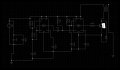
This is simplified schematic. Driver circuit is working as expected but I am getting HV spikes on Ignition coil terminals. Transformer on this schematic is ignition coil. I have ignition coil positive directly connected to battery positive. Ignition coil negative is conected to mosfet drain. Coil secondary positive goes to the fence and negative to the earth.(via metal rod stuck in soil). I can control duty cycle and frequency with 555 timers and everything is working perfectly and I am getting decent HV arcs on output. Problem is that I am getting HV spikes (I can also feel them by touching igniton coil primary terminals) between igntion coil primary terminals.
 

Attachments

Last edited:

Dodgydave

Joined Jun 22, 2012
11,395
I would drop the 555 supply down to 9V with a 7809 regulator and 100uF cap and 100nF cap, with a 1N4007 in series with the regulator Positive feed from 12V, this should isolate the pulses from the 555 chips. Also adding an UF4007 back emf diode across the mosfet D,S. Try a Uf4007 in series with the coil Positive too.
 
Last edited:

Hymie

Joined Mar 30, 2018
1,347
Given the back emf from the collapsing coil field, I’m surprised the 555 timers can withstand more than a few cycles of the circuit operation.

Besides Dodgydave’s suggestions, you could place a diode (1N4007) in the 12V supply to the coil and try to limit the back emf voltage with a snubber network across the primary winding coil.
 
Top