Facebook
 Google
 GitHub
 Linkedin
Hey ya all how ya doing?
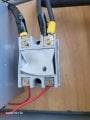
Im just looking for a bit of advice I am attempting to set up a a control box for a 220-240V system. I recently thought I was prepared but I melted the relay I bought, It 1 Was the wrong type 2 Cheep china mislabeled part. Im looking for some one to help me design a system, I am even willing to pay for your time. This is way over my head and Im just glad I didnt start a fire.
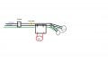
1, 50Amp Breaker, 2 is Amp meter, 3 Is SSR With control of any type currently use a pot, 4 Is 2 5500W Heating Elements
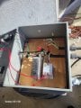
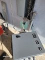
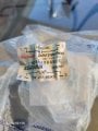
Below I Have posted images of the burnt relay Image 1,4,6, are the destroyed relay
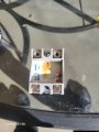
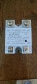
Images 2,5 are the Old relay I was using.
Of you care to just throw some information my way I apricate it, If you can tell me what parts I need where to get them and how to wire them I will pay the Hero of my day. Im under the impression that my relay melted due to it being mislabeled... Please prove me wrong
Im just looking for a bit of advice I am attempting to set up a a control box for a 220-240V system. I recently thought I was prepared but I melted the relay I bought, It 1 Was the wrong type 2 Cheep china mislabeled part. Im looking for some one to help me design a system, I am even willing to pay for your time. This is way over my head and Im just glad I didnt start a fire.
1, 50Amp Breaker, 2 is Amp meter, 3 Is SSR With control of any type currently use a pot, 4 Is 2 5500W Heating Elements
Below I Have posted images of the burnt relay Image 1,4,6, are the destroyed relay
Images 2,5 are the Old relay I was using.
Of you care to just throw some information my way I apricate it, If you can tell me what parts I need where to get them and how to wire them I will pay the Hero of my day. Im under the impression that my relay melted due to it being mislabeled... Please prove me wrong
Attachments
-
 1 MB Views: 42
 -
 1.3 MB Views: 43
 -
 1.8 MB Views: 40
 -
 1,016.1 KB Views: 38
 -
 27.9 KB Views: 39
 -
 39 KB Views: 41