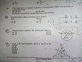
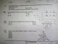
How would you find the equivalent resistance for question numbers 25?

WBahn

Joined Mar 31, 2012
33,075
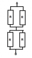
Consider the following circuit:
Req.png

What is the equivalent resistance between A and B?

Do you see that this is the series combination of two smaller two-resistor networks and that each of those smaller networks is the parallel combination of two resistors?

If you see that, then compare this network to the original network and see if you can tell that they are the same networks. Use the colored nodes that RBR1317 has shown to help you identify the connections.
 

WBahn

Joined Mar 31, 2012
33,075
Yes. Every piece of wire, the entire "node" in the middle of my diagram is exactly equivalent to every blue node in the other diagrams. Since they are assumed to be perfect conductors (or conductors with such low resistance that they might as well be perfect for our purposes) the voltage at any place along any of those nodes will be the same.

Let's call the top node 'A', the middle node 'M', and the bottom node 'B'. The netlist for all four circuits would be

R1 A M R
R2 A M R
R3 M B R
R4 M B R

Where the typical netlist format is used in which the first item is the reference designator (I just called them R1 through R4), the second and third items are the two nodes to which the resistor is connected (and since a resistor is symmetric it doesn't matter which what order we connect it in) and the final item is the resistance, which is just R in this case.

This is the description of the circuits that a simulator would see in each case, and so they are indistinguishable from one another.
 

Thread Starter

donaldparida

Joined Dec 16, 2016
26
@WBahn I have two concerns.
First, in the original circuit it seems that the wire with zero resistance is connected in parallel with the wire on which the point B(green point) lies. That should make the equivalent resistance between the end points of the both the mentioned wires zero. Is it incorrect to think that the wire with zero resistance is connected in the parallel with the wire on which point B lies?
Second, If the potential is same throughout the wire with zero potential then shouldn't the R3 and R4 be in series in your diagram rather than being in parallel in the wire with point B.
 
Last edited:

WBahn

Joined Mar 31, 2012
33,075
@WBahn I have two concerns.
First, in the original circuit it seems that the wire with zero resistance is connected in parallel with the wire on which the point B(green point) lies. That should make the equivalent resistance between the end points of the both the mentioned wires zero. Is it incorrect to think that the wire with zero resistance is connected with the wire on which point B lies?
Second, If the potential is same throughout the wire with zero potential then shouldn't the R3 and R4 be in series in your diagram rather than being in parallel in the wire with point B.

ALL wires (at this level of problem) have zero resistance. If, by "the wire with zero resistance" you mean the blue wire, then, no, it is NOT connected to the wire on which point B lies (the green wire). Put your finger anywhere on the blue wire. Without lifting it off the blue wire, can you slide your finger until it is on the green wire? No? Then they are not connected.

R3 and R4 are not in series because, to be in series, any and all current that flows through R3 must also flow through R4. If that is not the case, then they are not in series.
 

WBahn

Joined Mar 31, 2012
33,075
In order to be in parallel, two components must have the same voltage across them at all times. And by "same voltage" it means the same "symbolic voltage", not just a voltage that happens to have the same value. Looking at that way, then they are definitely not in parallel because the ends of the green wire are not connected to the same points as the ends of the blue wire.

Wires are generally not considered to be "in parallel" unless they are being treated as circuit components in which one side of the wire is distinguishable from the other side (which generally means that it is being treated as a small-valued resistor).
 

MrAl

Joined Jun 17, 2014
13,764
@RBR1317 , it looks to me like the previous one only. Now also the circuit divides into two branches and the equivalent resistance is zero due to a branch having zero resistance.
Hi there,

Try to think of how a test current flows from A to B in #23. This is not the same way as how the current would flow somehow from just point A or somehow from just point B, but from A to B, so the current flows say out of A and into B, or from out of B and into A, if we tested this with a current.

What you will see right away is that the current ALWAYS flows through BOTH sets of resistors, it never goes through just one set and then through a short alone, because the current must enter A and exit B (both points are involved not just one). The diagram is drawn to be a little deceiving so you have to think about it a little more. This means that any solution you come up with will have all four resistors involved in some way or another, and for a test current both points A and B are involved not just one or the other.

With that in mind, try this circuit again and see what you get. Dont try to just guess though, try to see how it works in your mind first by visualizing a test current that goes into A and out of B.
 
Last edited:

Thread Starter

donaldparida

Joined Dec 16, 2016
26
In order to be in parallel, two components must have the same voltage across them at all times. And by "same voltage" it means the same "symbolic voltage", not just a voltage that happens to have the same value.
@WBahn could you please clarify what you mean by "symbolic voltage"
 

WBahn

Joined Mar 31, 2012
33,075
@WBahn could you please clarify what you mean by "symbolic voltage"
It's basically just a way to refer to the voltage at a specific node (relative to an established reference point) or between a specific pair of nodes. It refers to a voltage that we have given a name (a symbol) to. For instance, you might have a circuit that has four nodes and at a particular point in time the voltage at node A (perhaps with the symbolic voltage Va) and the voltage at node B (perhaps with the symbolic voltage Vb) might both be 12 V. But while the actual voltage at both nodes are the same, the symbolic voltages are not because they are not the same node. You might have the voltage across Node G and Node K (perhaps with the symbolic voltage Vgk) and there might be some component, say R1, that is connected to Node G and to Node K and it might have 20 V across it. There might well be another resistor, R2, that also has 20 V across it, but unless it is also connected to Node G and to Node K, it does not have the same symbolic voltage across it.
 

Thread Starter

donaldparida

Joined Dec 16, 2016
26
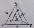
@WBahn Just for the sake of understanding the concept, if a resistor of resistance R is added between C and B in Q 25 how would the equivalent resistance be calculated?Donald_IMG_20161215_142222.jpg
My answer is 9r/19.
 
Last edited:

WBahn

Joined Mar 31, 2012
33,075
@WBahn Just for the sake of understanding the concept, if a resistor of resistance R is added between C and B in Q 25 how would the equivalent resistance be calculated
My answer is 9r/19.
Let's first establish some bounds so that we can sanity check out answer.

TriR1.jpg

If we ignore the two resistors connected to Node E, then from C to B we have two resistors of value R in parallel, making that R/2. That combines with the R/2 from A to C making a total or R through that route. That is then in parallel with the R from A to B making a total resistance from A to B of R/2. Adding in the resistors at Node E can only make this go down, so the actual resistance must be LESS than R/2. Since your resistance of 9R/19 is just under R/2, there is a good chance it is correct.

As a lower bound, we can consider the case when one of the resistors connected to Node E is replaced by a short. That makes the C-B path consist of R in parallel with R/2, which is R/3. This is in series with R/2 making 5R/6 along the A-C-B path. Putting this in parallel with the R from A-B yields 5R/11. So the actual resistance is MORE than this, and since 5/11 is slightly smaller than 9/19, your answer is still very much in the running.

Working through the full analysis, your answer is correct.

Good job.
 

Thread Starter

donaldparida

Joined Dec 16, 2016
26
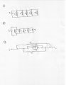
@WBahn , It seems at first sight of the first circuit that all the resistors of resistance r are connected in parallel and i have thus simplified it to the second circuit. But then on numbering the nodes and redrawing the circuit i got the third circuit.
I got the same equivalent resistance for all the three circuits which i think is a coincidence because i do not not know why the second circuit is equivalent to the first one (i drew that way because the in the first circuit it seems that all the resistors are in parallel).
I basically have two questions:Is the first circuit equivalent to the second circuit or the third circuit or both? Why is the second circuit equivalent to the first one if it is so?
Scan4.jpg
 
Last edited:

WBahn

Joined Mar 31, 2012
33,075
They are all three equivalent. In all three cases all of the resistors are in parallel. In all three cases each resistor is connected directly across the voltage source.
 

Thread Starter

donaldparida

Joined Dec 16, 2016
26
IMG_20161215_142222.jpg
@WBahn One more concern. For question number 23, if a resistor of resistance R is added to the lowest wire, what would be the equivalent resistance between A and B?
My answer is R. I simplified the circuit by redrawing the nodes in a convenient manner and then applied the Wheatstone bridge principle.
 
Top