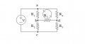
In general kirchhoff's voltage law=mesh analysis. The wiki site looks OK http://en.wikipedia.org/wiki/Mesh_analysis But you will for sure find a lot of stuff regarding this using Google. Take some time to find the explanation that you find fit your way of understanding best
I would analyze it by inspection running the numbers in my head. Not that I'm particularly good at doing that in general, but this one is easy. You have a Norton current source on the left and a Thevenin voltage source on the right. You can transform either side and play all kinds of mind games with it.
resistance of ideal current source is infinite. so the current produced by voltage source is not going to go towards current source and hence the two resistances 1 ohm and 3 ohm are in series connected to 4 V supply. current can be calculated from here. current flowing in series resistances are same.
since now we figured out the current flowing because of voltage source its easy to calculate current due to current source.
now all currents are figured out. apply ohms law V = IR to calculate the voltage drop across individual resistors.
...the current produced by voltage source is not going to go towards current source and hence the two resistances 1 ohm and 3 ohm are in series connected to 4 V supply. current can be calculated from here. current flowing in series resistances are same.
resistance of ideal current source is infinite. so the current produced by voltage source is not going to go towards current source and hence the two resistances 1 ohm and 3 ohm are in series connected to 4 V supply. current can be calculated from here. current flowing in series resistances are same.
since now we figured out the current flowing because of voltage source its easy to calculate current due to current source.
now all currents are figured out. apply ohms law V = IR to calculate the voltage drop across individual resistors.
Your reasoning is way off. The two resistors are most definitely not in series. In fact, the currents in them differ by 8A.
There are at least half a dozen ways to analyze the circuit and they are all pretty much the same difficult. I would recommend analyzing it several different ways to make sure you get the same answer. The simplest one, as I see it, is to convert the 8A current source and the 1R resistor into an equivalent thevenin circuit. At that point you can determine the current in 3R resistor and the voltage source and then use that to determine the current in the 1R resistor (in the original circuit). You can do it all quite easily in your head.
i am telling the general case, not specific for this problem.
its my crude method for analyzing simple circuits directly without source transformation and without using any complicated equation.
remove the current source. see them as voltage source connected to 1 ohm and 3 ohm resistance. and now they are in series. so there are (3+1) ohm resistance connected to voltage source. therefore current leaving/entering the voltage source is 4/(3+1) = 1A.
now current leaving/entering the current source is given as 8A. This 8 ampere current will flow from 1 ohm resistor (this time i have neglected voltage source).
total current from 1 ohm resistor is the algebric sum of (what found neglecting voltage source) + (what found neglecting current source).
You are describing the superposition method, and that is certainly a good method for this problem. Personally, I would not describe this as a crude method.
You are describing the superposition method, and that is certainly a good method for this problem. Personally, I would not describe this as a crude method.
yes i used the superposition method but it was with some modification. That modification is good for this particular problem but it's not a good idea to adopt such methods. so i removed the attachment from my last post so that OP don't learn the bad habits.
You are describing the superposition method, and that is certainly a good method for this problem. Personally, I would not describe this as a crude method.
He's describing the concept of superposition, but not doing so correctly or validly. You don't "neglect" the sources, you turn them off (i.e., set them to zero output). For a current source, this means effectively removing it from the circuit. But for a voltage source it means shorting it so that it have 0V across it but no restriction on the current rhrough it.
That his method is invalid is evidenced by the fact that it produces the wrong answer for this problem. He gets 1A flowing downward in the 1R resistor when neglecting the current source and 8A flowing downward in it when neglecting the voltage source for a total of 9V. But, used properly, superposition gives 1A flowing downward with the current source turned off and 6A flowing downward when the voltage source is turned off.
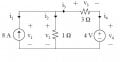
Thanks guys! Your help is invaluable to me as I am new to the concepts of Kirchhoff's laws!! So in looking at another example, how would you make a KVL equation for the loop indicated? The thing that really gets me confused is R3, what is the polarity of the voltage across it? How do you deal with it?
assign polarity based on your loop. Key is being consistent, your final answer will correct itself. In these problems, if your final answer is negative, it means that current runs in the direction opposite to what you assigned.
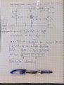
Attached is my attempt at solving this circuit using the node method.
Please, if you can, tell me where my mistakes are in my thought process.
The thing that really gets me is the signs, the signs of the current and voltage. I suppose you can find if you got the voltage polarity correct buy going around the given loop and seeing if the voltage sums to zero. Direction of current still confuses me.
And if I don't understand the former, how can I use them to find the sign of the wattage!
I thought voltage and current sources gave out power therefore their power was given in -W. But upon entering the answers I got current power in watts wrong. I entered -56W but the correct answer was +56W.
The questions were:
The value (in Volts) of
v1
is: 7
correct
The value (in Amperes) of
i4
is: 1
correct
The power (in watts) coming out of the current source: -56
incorrect
The power (in watts) coming out of the voltage source: -4
 Facebook
 Google
 GitHub
 Linkedin
 11.9 KB Views: 96