The object is to set of an alarm when the flow of water stops or drastically decreases using a hall effect flow sensor.
I have plumbed a flow sensor similar to: https://www.ebay.com/itm/Water-flow...085353?hash=item2ca4998469:g:1SAAAOSw4UtWSqc6 in the salt water line on my boat between the sea strainer and the suction pump for engine cooling over a 'salt to fresh water' heat exchanger .
When the incoming water flow stops, say, due to a blocked sea suction, or the pump impeller fails , the water flow will diminish to a large extend and the hall effect sensor should than operate a relay which in turn sets of a high pitch 12V buzzer alarm.
While the sensor is rotating the pulses it generates are used to keep the alarm in the OFF state.
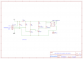
I have built a circuit from a diagram, I found online, but it keeps blowing the transistors.
Can anyone please suggest a working circuit: only on 12V DC.
The diagram should have a linear pot meter to set a minimum flow rate.
Many thanks for any help Gentlemen
I have plumbed a flow sensor similar to: https://www.ebay.com/itm/Water-flow...085353?hash=item2ca4998469:g:1SAAAOSw4UtWSqc6 in the salt water line on my boat between the sea strainer and the suction pump for engine cooling over a 'salt to fresh water' heat exchanger .
When the incoming water flow stops, say, due to a blocked sea suction, or the pump impeller fails , the water flow will diminish to a large extend and the hall effect sensor should than operate a relay which in turn sets of a high pitch 12V buzzer alarm.
While the sensor is rotating the pulses it generates are used to keep the alarm in the OFF state.
I have built a circuit from a diagram, I found online, but it keeps blowing the transistors.
Can anyone please suggest a working circuit: only on 12V DC.
The diagram should have a linear pot meter to set a minimum flow rate.
Many thanks for any help Gentlemen