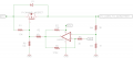
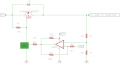
Was the boost regulator providing more than 20V when the MOSFET fried? If not, and the regulator has no reverse current protection, then current through the MOSFET body diode may have been enough to do the damage.
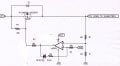
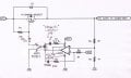
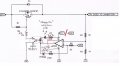
I added R7 and R8 as the attached and tried without R6 also and each time I connect the load it doesn't turn it off, only heating the MOSFET until it burns.
As to R8, I tried also to connect it between gate and Vout, also didn't matter. Maybe it needs an extra capacitor? are you sure all the connections and components locations are correct and it is only an Oscillation issues?
also where to connect the oscilloscope and how to determine if its an oscillation issue?
I don't think R7 should be there, and definitely R8 should be removed.
With R8, the FET will be turned on all the time.
Also, with the hysteresis resistor R6, there is a path for the FET to be partly turned on.
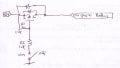
I'll have a go at drawing a circuit up of what I think could fix it..
To turn the FET on, the gate needs to be pulled towards GND by at least 12V below the 27V. To turn the FET off there must be NO connection to GND at all. The LM393 output being off in the same as not connected.
I'm not sure where you keep getting these extra resistors from.
Try this for a test to make sure the problem is not the FET switching...
It should work without that. But get rid of R8.
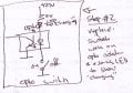
Try the circuit I added to the previous post to make sure that part works, then we will work on the control part.
An opto will isolate any path to ground from the control circuitry.
It is probably a bit overkill but I find them a really useful device for level conversion, not just isolation. So I use them a lot.
I have tested now the switch as in #25 you suggested and it works fine. also when I tested the lm393 alone without the FET, it worked also fine.
As to opto, why to add this opto isolator? you don't think that the comparator alone can handle the on/off switch if considering changing or adding the resistors values?
Besides that, can you offer an opto simple model for reference? as I don't have it available and it will take time to get it.
An opto is the easiest to isolate the current path to GND via R6 for example. Even when the LM393 output is off, there is still a resistive path to GND from the FET gate. There needs to be only one path, and that needs to go completely open when off. No extra resistors from the gate to even 5V as that will turn the FET on. The gate volts needs to go to 27V when off. Have you measured the gate volts between on and off?
A buffer transistor with a LM393 pullup resistor could be used, but the polarity of the LM393 switching will need to be reversed as the transistor will invert the sense, and that is ok too. But I like optos.
The MOSFET connections are correct. it is working as I noted in the test I made an Hour ago.
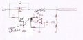
as to adding the opto, I am trying to revise the connections as you noted with the opto and it is not clear for the diode or diodes you added to R7, can you write it more clearly?
please check the revised and advice if all is correct?
In addition, can you specify for an opto model you use that can do this job?
I just had a thought. If the FET is being turned on via the +5V, try adding a diode as shown...
It will block the current flowing via the +5V supply. And your R7 is not needed.
have you got a bypass capacitor across the LM393?
I'll redo the opto circuit soon if you still want it.
Here is the updated Opto circuit..
But I will be interested to see if just adding the diode in line with R6 works.
And a capacitor across the LM393 is needed for stability.
have you measured the gate volts to see if it goes from 27V when off to about half that when on?
It must go to 27V (or the same as your power supply) when off. Otherwise it will be on a bit, or fully.
As for the opto PC817, I have noticed in the data sheet that the max Voltage Input is 1.4v - Is that refers to pin 1? if that is so, how it can accept a 27v as in the schematic as a Vin? or I got it wrong? also the peak voltage is 6v, is that for pulse? can you please advice?
All LEDs have a low forward volts. But as they are current devices, a series resistor is used to set the current. If you were to hook the LED onto, say 5V (or 27V), but without the current limiting resistor, the LED would still light, but very bright, just before it blew.
The forward voltage is used in the calculation of the resistor value. For example, on 5V supply, to calculate the resistor for 10mA current through the LED...
R=E/I so....
R = (5V supply - LED Fwd V)/required current
= (5-1.4)/.01
= 3.6/.01
= 360 Ohms.
I hope that helps.
Thanks for the explanation. but I didn't understand if to leave the comparator Vin to be 27? or to change it to 5v?
1. As for the 2.2k, 27/2.2k=11mA but the opto input voltage will be 25.5v... is that ok? (meaning - to high for the opto pin#1)
2. And if changing the comparator input to 5v, so the output will be 3.5v (the comp "eats" 1.5v), so opto pin#1 voltage will 1.4v with 210R in series : 3.5-1.4v/0.01=210R - Is this assumption is correct?
It could be an idea to make R3 and R4 30K and 10K to lower the battery discharge a bit.
And running the LM393 on 5V should be ok I think.
I don't know what you mean by "(the comp "eats" 1.5v)" .
The o/p saturation voltage at 10mA will be about 700mV and the LED current is not critical in any case.
Also, the LED forward voltage will probably not be exactly 1.4V, but just take these readings as a ballpark indication.
Try 330R for the 5V, or a 390R. It will be best to keep the current under 10mA.
As for the "opto pin#1 voltage", it can be anything above the minimum 1.4V, just as long as you limit the current.
For example ( not for you to use! ) at a diode current of 10mA, and a 250V input voltage, it would require a resistor (ignoring the 1.4V drop) of 250/0.01 = 25K ohms. At higher voltages, the power dissipation needs to be taken into consideration.
P=E*I so.... resistor power dissipation = 250V*0.01A = 2.5Watts. If you were to run an LED at 10mA off 250V, the resistor will get hot as it has to dissipate 2.5Watts. So one would use a 5 Watt resistor, and mount it with free air circulation to keep it cool.
"I don't know what you mean by "(the comp "eats" 1.5v)" - This comparator self consumption is 1.5v.
Just to understand the point regarding changing R3/R4 X10 times resistance, can you please explain your meaning for "It could be an idea to make R3 and R4 30K and 10K to lower the battery discharge a bit"?

 Facebook
 Google
 GitHub
 Linkedin