How to test a 12mm piezoelectric buzzer ?

Thread Starter

q12x

Joined Sep 25, 2015
1,657
I bought these 12mm Piezoelectric Copper Buzzers for a long time: IMG_20200613_044133.jpg (click on image to enlarge)
But i never being able to put them to work. I sincerely dont know how to make them to work.
I only can imagine how could they work, but in reality.. i simply dont know. Its the ugly truth.
Today I get the courage to write here and i thought to also put you the specifications.
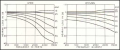
I was guessing that they could be dependent of frequency, but im not very sure. So when i look over their specifications from ebay, it stated there: Resonant frequency 8.5KHz. I think they are dependent of frequency !
My way of testing ANY buzzer is the old way: Put some low voltage (2V) on the pins, and listen if they make a click sound in the same time of the connection, and repeatedly make many conections like that to hear them click.
But these 12mm piezo are not making ANY click sound whatsoever. I raised the voltage progressively up to 30V and barely any sound, like 1.5 from 100. Extremely low sound at maximum voltage i have. I even made them a mini chamber with a hole in the middle (from paper) to amplify the sound and it did in its way, but again, it amplify it like 1%. Extremely inefficient.
These are the tests I did in the past !!! Now im only sharing my bad experience and shame (and stupidity).
But now, im thinking maybe they can work LOUD on a very specific frequency. Again, im only guessing.
I want to believe they are not dead or damaged.
here is the exact link to what i have: https://www.ebay.com/itm/10Pcs-12mm...426354?hash=item58cbafecf2:g:jo8AAOSwyZ5UmotM
and a little bit down in the page, if you scroll down, you can find a table with specifications.
In my defense, i worked very few times with audio circuits and buzzers in my entire life. And also im not an electronist, im a hobbyist so im doing it rarely. And i have to remember stuff from 30 years ago. :)
>>> All i want from you is to give me a circuit, a very simple one if possible, to efficiently make these piezo buzzers work loud/normal.
>>> Or to help me understand how to properly TEST them, because clearly I have no clue with my antique knowledge.
I imagine: i will need a circuit that will generate 8.5KHz for these specific piezo.
A secondary problem:
I also have another model of buzzer:
IMG_20200613_044217.jpg(click on image to enlarge)
It's ebay page:
https://www.ebay.com/itm/10PCS-5V-P...938581?hash=item1ed9040695:g:OnsAAOSwOgdYvV1s
They say are working at: "Frequency: AC/2KHz" ;
so... AC it's alternative current at 2KHz ?
I only tested them at DC 5V max; and the frequency of my finger moving quickly over the contact, which is probably 22.45481 mHz?
They are also make little sound, but I can hear them if i close my ear to it, so its more louder than the piezo. But still very quiet for practical usages.

Sorry for the long text but it gets very quickly, very complicated.
Thank you.
 
Last edited:

KeithWalker

Joined Jul 10, 2017
3,063
I bought these 12mm Piezoelectric Copper Buzzers for a long time: View attachment 209579 (click on image to enlarge)

>>> All i want from you is to give me a circuit, a very simple one if possible, to efficiently make these piezo buzzers work loud/normal.
>>> Or to help me understand how to properly TEST them, because clearly I have no clue with my antique knowledge.
I imagine: i will need a circuit that will generate 8.5KHz for these specific piezo.
A secondary problem:
Make an astable multivibrator circuit using a LM555 timer. I have attached the data sheet. It shows you the circuit you need in the applications section with instructions on selecting the right components for the frequency that you need. The 555 chip has a push/pull output so you can connect the ceramic transducer directly between the output and either supply + or circuit common.
Regards,
Keith.
https://www.ti.com/lit/ds/symlink/lm555.pdf?&ts=1589807336993
 

KeithWalker

Joined Jul 10, 2017
3,063
How do you connect the leads on those things?
You should have got the ones that already have the wires attached. Solder the end of a red insulated wire fairly close to the edge of the center silver disk. Solder a black insulated wire onto the gold disk, on the same side.
. Observe the polarity when you connect it in circuit. Reversing it will not damage it but it will work best the right way round.
When you test it, the frequency does not have to be at resonance. It will work over quite a wide range. Have fun.
Keith.
Drawing1.jpg
 
Last edited:

KeithWalker

Joined Jul 10, 2017
3,063
You don't. You clamp them between a resonating surface (copper side) and a spring contact presses on the central white piezo element.
I've not had much success soldering them...
The element in the center should have a thin layer of silver/white metal on it. This is how I do it:
New-1.jpg
 

Thread Starter

q12x

Joined Sep 25, 2015
1,657
You should have got the ones that already have the wires attached.
You are very right. But...
I buy the cheapest from ebay, and they come as they come. 10pcs for 1$. I dont bargain with that.
I buy them for experimenting and learning. Also to stock.
I actually was thinking i will get a larger version, but i learned this way to read their description every single time before buying. I didnt know back then, that they even had a description/specifications. Now I do. Lesson learned.

Solder the end of a red insulated wire fairly close to the edge of the center silver disk. Solder a black insulated wire onto the gold disk, on the same side.
Probably you should use the "inner" word instead of "center". For a minute i stared to your text to understand what you wanted to say. :)
This information about how to solder is VERY interesting; I did not know it at all and i praise you for it. Very good this mentioning.
>>>> Do you know why should be soldered so close ?
I made the contacts (with touching wires or soldering) wherever on that inner disc, without thinking at "where" to make the contacts. I remember every piezo i've seen in my life, they all had wires as you describe. I never seen with wire in the middle of the inner circle !!! So you are very right. A very tricky detail.
I also didnt pay attention to the polarity as well, and i connected it how i could, every time. Another tricky detail and i thank you very much for it.
 

Thread Starter

q12x

Joined Sep 25, 2015
1,657
Victory 50%.
I made the circuit and it works pretty well, pretty loud with a buzzer.
But it is not working at all with the piezo.
I have no idea how to make that thing make any noise.
This circuit unfortunately works with 3 - 5V. I give it 8V and I burn one 555 IC.
dBenzin99_ziub_13 - piezo  copy 2.jpg (click on image to enlarge)
I still want to know how to TEST a piezo.
You are right, the white metal on it is somewhat solderable. I think is a conductive paint that is NOT that well adhered to the ceramic piece. It is literally peeling off very easy. I recomend to use a very thin copper wire 0.15mm only to this surface. And is also burned very quickly if you stick too long the iron on it. Cold contact is necessary. What i did, I solder OnlY the golden piece and I touch with a connected wire, the inner piezo circle to check for sound clicks or hums.
Thank you so far, you are great guys !
 
Last edited:

KeithWalker

Joined Jul 10, 2017
3,063
Victory 50%.
I made the circuit and it works pretty well, pretty loud with a buzzer.
But it is not working at all with the piezo.
I have no idea how to make that thing make any noise.
This circuit unfortunately works with 3 - 5V. I give it 8V and I burn one 555 IC.
Try the circuit with a 9 volt battery. It should give you some sound if the frequency is in the right ball park. For best results, the edges of the gold disk should be clamped to something ridgid so the center can move to produce sound.
Keith
 

Audioguru again

Joined Oct 21, 2019
6,672
You bought the cheapest buzzers you could find. Why does the ebay seller say they are copper in one sentence then say they are brass in another sentence? Are they so cheap because they are defective or are fakes? Copper paint looks good but does not work.

You put 2VDC and expected to hear something, maybe hear a click? But a piezo transducer like you have needs AC from an oscillator, not DC from a battery.

Your 555 circuit burned but should work fine up to a power supply voltage of 18V. Is it the cheapest 555 you could find on ebay and is it cheap because it is defective or is a fake?

Maybe the piezo transducers are made wrong and are shorted? Then even a good quality 555 will burn.
Maybe the piezo transducers are made wrong and were thrown away (then sold on ebay) because their frequency is higher than the 8.5kHz they were supposed to produce? Maybe the manufacturer threw them away because many people cannot hear sounds as high as 8.5kHz or higher? Can you hear that high? Most men 45 years old and older cannot.
Why did you select the tiny piezos with such a high frequency? What will it be used for?

A piezo buzzer has a transistor oscillator in it. The piezo disc has 3 sections so that one section has a wire that gives positive feedback to the transistor so that the circuit works at the resonant (loudest) frequency of the piezo and its enclosure.
The piezo transducers you have need to have the frequency of the 555 oscillator accurately adjusted to match the resonant frequency of the piezo which might be 7kHz to 9kHz. Then you need to mount the piezo in a suitable enclosure that is also accurately adjusted.
 

Attachments

Thread Starter

q12x

Joined Sep 25, 2015
1,657
to: Audioguru again
-Im not deaf : ) hahaha Not at all. And my ears are clean also. Its not that. And im not THAT old either. Im 40. I consider i still have normal hearing.
-These VERY little piezo devices are not damaged at all. I did get a click sound from them but at around 25V DC from my variable power supply. Being very little in diameter they are probably not that loud on lower voltage. I did tried with a larger diameter (like 4cm) piezo some very long time ago, and I could get those click sounds from touching with the wire on them at 3V probably. So a normal behaviour, is all i remember. I didnt think these little diameter piezo will have such pretentious characteristics. Lesson learned i suppose.
-All i really need is some sound emitting devices, small enough and on low voltage and very loud.
Then... i have another idea. What you recommend? What audio device you already have in your stock, or that you used successfully along the years? I really dont care how it looks, as long as it does its job. It can be unortodox devices too. My question, is you to suggest me the normal devices you think are the ok ones. Because, myself so far, i gathered some weird stuff that "kind of works".
---
to: KeithWalker
-I really like your suggestion of clamping "to something rigid so the center can move to produce sound." I tried something in this direction but probably not that well. I tried to copy a normal buzzer structure. It did amplified very little, but still not good enough. (again, im not deaf, you should trust me on my word). I had a very short iron tube milled and this piezo was fitting that hole enough to be stick there with a bit of poxipol. I did this experiment some time ago and I dont have the device anymore. I even put a little paper with a hole in the middle in the hope it will amplify more. But i still could not get it to normal.
---
-I have another bright idea:
-Can anyone conceive for me a dedicated circuit having normal components, that will create this 8.5kHz resonance characteristic for my piezo? If possible of course and if you like a bit of challenge. I still believe i can make them work.
Thank you for all your support so far !
 

Audioguru again

Joined Oct 21, 2019
6,672
My hearing graph shows that you probably have a problem hearing a sound frequency as high as 8.5kHz and the cheap junk piezos you bought might be higher, but they might not even work.

A simple LM555 or NE555 oscillator can use a trimpot for you to adjust its frequency to the resonant frequency of the piezo and its enclosure. But it will be difficult to adjust and its frequency will change with temperature and battery voltage changes. When they change then the sound level will also change.

You need to use a piezo buzzer (beeper) that is powered from DC instead that does not need adjustment.
 

Thread Starter

q12x

Joined Sep 25, 2015
1,657
to:Audioguru again
- I understood your hearing graph and i looked on it. You should trust me on my word, it is not my hearing the problem. I can see you dont trust me and insisting on this direction. I suggest to trust me.
- I would suggest to you to buy (1$) the same product and test it as i did and see you will get the same results as me, and after that, test it your way until you can get a good result(hopefully). Its only a suggestion, i dont want you to think im trying to sell things. My only interest is to understand them.
-The 5V passive buzzer, I put the picture for it and the ebay link in my original question, that is sounding acceptable loud, but is not Very loud. Is loud enough. Unfortunatly I dont have a decibel meter so you must understand this method of explaining.
I dont use battery. I have a 0-30V variable power supply. Is very helpful.
And for the duration of an experiment, the temperature is stable enough, until i can find the correct resonance freq.
You are giving me a good suggestion here and i will try it, by using a trimpot in the same 555 circuit.
You said: " You need to use a piezo buzzer (beeper) that is powered from DC instead that does not need adjustment. "
-And thats why i asked what (commercial) sound emmiter components can you suggest to me?
 
Top