 Facebook
 Google
 GitHub
 Linkedin
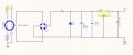
Hi everyone, now I'm looking for the current transformer to provides the power in case of single-wire (Neutral missing)
so I unofficially call "CT power supply" circuit as attached files
Circuit spec:
- when Iprimary = 1A to 60A , Output must be 3.3Vdc (load: 5mA) for supply MCU
So I would like to know how to select CT burden for this circuit?
so I unofficially call "CT power supply" circuit as attached files
Circuit spec:
- when Iprimary = 1A to 60A , Output must be 3.3Vdc (load: 5mA) for supply MCU
So I would like to know how to select CT burden for this circuit?
Attachments
-
 83.4 KB Views: 25


")


