Facebook
 Google
 GitHub
 Linkedin
I am using this "SC18IS606" I2C-bus to SPI bridge chip in the circuit.
The datasheet is available under the link below.
https://www.nxp.com/docs/en/data-sheet/SC18IS606.pdf
I understand the address pins A0, A1, A2. I can have eight chips on one I2C bus with eight unique address set by address pins A0, A1, A2. I will connect these pins to VDD or GND accordingly.
I am not sure about how do I connect the following pins in the circuit.
SS0/GPIO0
SS1/GPIO1
SS2/GPIO2
I am not using these pins as GPIO.
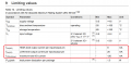
Last question is what is the current consumption of this chip ? I am wondering about the power supply current.
The datasheet is available under the link below.
https://www.nxp.com/docs/en/data-sheet/SC18IS606.pdf
I understand the address pins A0, A1, A2. I can have eight chips on one I2C bus with eight unique address set by address pins A0, A1, A2. I will connect these pins to VDD or GND accordingly.
I am not sure about how do I connect the following pins in the circuit.
SS0/GPIO0
SS1/GPIO1
SS2/GPIO2
I am not using these pins as GPIO.
Last question is what is the current consumption of this chip ? I am wondering about the power supply current.