How to Search for Transistor Replacement/Alternative

Thread Starter

patrickstefanski

Joined Apr 15, 2017
49
Hello.
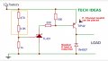
The circuit I am trying to make requires a TIP42 PNP transistor. (Datasheet)
I want to order along with my other components from digikey, but digikey doesn't have an SMD version of this transistor.

Rather than ask "What's a good replacement?" I'm asking "What are the key data points to look for when searching for a replacement?" What are the must haves? What are the "good to get as close as you could"s. That kind of thing. I have no electrical engineering background, so those data sheets can be a bit overwhelming. If I could narrow down the attributes to search for that would be really helpful. Thanks !
 

WBahn

Joined Mar 31, 2012
29,976
What is important depends on the specific application it is being used in. For some circuits parameter x is critical and your replacement should be at least as good, for a different circuit (or perhaps even a different place in the same circuit) parameter x could be a complete don't-care.
 

dl324

Joined Mar 30, 2015
16,841
I'm asking "What are the key data points to look for when searching for a replacement?" What are the must haves?
You need to analyze the circuit and determine which parameters are important. Then pick another transistor that satisfies those requirements. Just like the person who did the original design had to do.

If you want someone else to do that for you, you should post a schematic.
 

Dodgydave

Joined Jun 22, 2012
11,284
Does your circuit need 6 Amps or is it working at 60 V,,, if neither then choose another transistor that fits your needs..
 

Thread Starter

patrickstefanski

Joined Apr 15, 2017
49
You need to analyze the circuit and determine which parameters are important. Then pick another transistor that satisfies those requirements. Just like the person who did the original design had to do.

If you want someone else to do that for you, you should post a schematic.
No, I definitely don't want to bother anyone or ask any one to do my work for me. Quite the opposite. I'm new to this and trying to understand things a bit a better so I don't have to ask for help all the time. My lack of information provided isn't laziness, it's lack of understanding in what is needed. I am sorry.

This is the circuit I am working on (attached). It comes from a Youtube video here:

It's a way to power down my project before I damage the batteries. The batteries are 12v (3S lipo) and they run a motor that has a stall current of 20A. I don't think this transistor would have to be line with that motor, so not sure if that 20A affects this? Not sure.
 

Attachments

crutschow

Joined Mar 14, 2008
34,281
I don't think this transistor would have to be line with that motor,
Yes it does.
Otherwise how would it keep the motor from draining the battery?
Or is there another transistor/circuit controlling the motor?

So the TIP42 is not adequate for you application if the motor current goes through it.
Instead I suggest a P-MOSFET that can handle 20A with a voltage rating of at least 20V.
Look for one that has an ON-resistance of less than 50mΩ so you don't need a heatsink.
The other MOSFET parameters are of little interest in your application.

That circuit has a design error.
Reduce the value of the 15k resistor to about 1k to carry the bias current of the TL431 near the trip point.
 

dl324

Joined Mar 30, 2015
16,841
The batteries are 12v (3S lipo) and they run a motor that has a stall current of 20A. I don't think this transistor would have to be line with that motor, so not sure if that 20A affects this? Not sure.
The transistor needs to handle the load current, which is 20A in your case. TIP42 isn't sufficient:
1582050048074.png

YouTube isn't a good source of information. Most of what I've watched is crap; except for the cat videos.
 

Audioguru again

Joined Oct 21, 2019
6,672
The absolute maximum current for the TIP42 power transistor is 6A when its metal tab is mounted on a huge heatsink. That is why The TIP42 is large and is not a tiny surface-mount transistor.
Since your load maximum is 20A (!) then you must use a larger transistor with a maximum current rating of at least 20A. A larger heatsink also must be used.

You should look at videos about electronics where the author talks about the circuit. That circuit reduces voltage to your robot all the time unless you use a high power P-channel Mosfet.
Did you notice how he solders with the filthy dirty soldering iron? Solder is supposed to be applied to the wires to be soldered, not to the soldering iron.
 

dl324

Joined Mar 30, 2015
16,841
Based on that comment, I watched the video. Or tried to. Waste of time. Why do guys one step removed from a gorilla make videos of their hairy arms???
 

Thread Starter

patrickstefanski

Joined Apr 15, 2017
49
The transistor needs to handle the load current, which is 20A in your case. TIP42 isn't sufficient:


YouTube isn't a good source of information. Most of what I've watched is crap; except for the cat videos.
Agreed. Cat videos are fantastic.

Question about handling the load current; sorry if this is dumb.
Is there a way to branch a circuit like this off from the motor so that it wouldn't have to affected by the full current of the motor if it were to draw 20A?

Ive attached a rough drawing of my planned circuit. In this drawing would my linear regulator also have to be able to handle 20A? If not, can I place a cutoff circuit like the one above on another "branch" like shown which isn't in line with the motor? Or if that type of circuit is always draining, maybe I can monitor a voltage divider on my arduino and just cut off the motor in software if the battery gets to low. Is that a better solution? Or is there a different issue that crops up from that solution?

I know YouTube isn't the best place to find things. One of my biggest problems as a beginner is not even knowing what components exist, let alone how to use them. I was looking for a way to shut down my batteries before they got too low, and when I searched that is the type of thing that comes up first. I want to learn as much as I can about this stuff, but at the moment can't afford to go back to school for it. So i'm just using hte internet to the best of my ability.
 

Attachments

dl324

Joined Mar 30, 2015
16,841
Ive attached a rough drawing of my planned circuit. In this drawing would my linear regulator also have to be able to handle 20A?
I don't see any way around that. You want to disconnect the battery from the load under a low voltage condition. That switch device needs to be able to handle the full load current.
 

Thread Starter

patrickstefanski

Joined Apr 15, 2017
49
I don't see any way around that. You want to disconnect the battery from the load under a low voltage condition. That switch device needs to be able to handle the full load current.

Let me start by saying I appreciate the all the replies. This is very helpful.

As far as the switch. My goal was to use a relay (rated to 20A) so that I could use a smaller switch that wouldn't have to handle that load. Is that not a correct thinking? Is there a way I can use a smaller power switch (space isn't available) and a relay to switch on the higher current circuit with a lighter rated switch?
 

dl324

Joined Mar 30, 2015
16,841
One more thing, My arduino DEFINITELY can't handle 20A. How is that protected in anyway?
The Arduino isn't at risk. You could use it to detect low voltage and control the relay.

You probably want some hysteresis in the voltage detection so the switch doesn't oscillate between open and closed.
 

Thread Starter

patrickstefanski

Joined Apr 15, 2017
49
The Arduino isn't at risk. You could use it to detect low voltage and control the relay.

You probably want some hysteresis in the voltage detection so the switch doesn't oscillate between open and closed.
Okay maybe this last question will clear some things up for me:

In my drawing above. Why is the Linear Regulator in Danger, but the Arduino is safe? Is it because it is one component removed from the 12V Bus? If that's the case, are there any "buffer" components I can use between the power bus and the linear regulator/voltage monitoring circuit in lieu of a higher rated regulator.
 

dl324

Joined Mar 30, 2015
16,841
Why is the Linear Regulator in Danger, but the Arduino is safe?
I didn't see any mention that the regulator was at risk. If you have a snubber diode to supress the back EMF voltage spike when the motor is turned off, nothing will see a higher than expected voltage.

If power is removed from the regulator when you disconnect the battery, then your control circuit won't work unless the Arduino is used to keep the relay energized. Then removing power from it would cause the relay to open.
 
Top