Facebook
 Google
 GitHub
 Linkedin

The use of 0.1uf ceramic capacitors would surely help me out. I have included them in design 3 which uses 555 timer, 74HC164 and a driver TC4426. so all of my LDOs,555 and other ICs have a decoupling cap of 10uf and 0.1uf ceramic.And By The Way -
In all three post #1 schematics, the 555 oscillator period is 10 seconds. At this rate, a 40-second delay should be decoded as 4 clock cycles. However, in all schematics the output is activated after 8 clock cycles. Thus, the actual delay between pressing the manual switch and activating the lock mechanism is 1 minute 20 seconds.
Also, in schematics #2 and #3 it looks like the Manual switch must be pressed/flipped/toggled for a full clock cycle to guarantee that a logic 1 is clocked into the shift register's first stage. This is either 5 or 10 seconds, depending on the intent of the oscillator frequency. The schematic #1 circuit is different, and it is not clear what the Manual input is supposed to do. It looks like it is just a clock output disable, done by grounding the Q2 base.
ak
I have already started implementing design 3 and you are right about the clock pulse needed to be held high for 5 - 10 seconds depending on 555 timer frequency. this is by design. the shift register transitions from low to high pulse. so a manual trigger is needed to be held high for atleast that amount of time in order for the first stage (Q1) of the shift register to turned on. then the Q7(last bit) of the shift register turns on the driver.
this prevents someone drilling a hole in the box that the circuit will be placed inside and poking around with a screwdriver and hoping they can get a short somewhere and have the output of the driver go high. I know this seems far fetched but I want to safeguard against most possible attacks.
in my PCB schematic, the 9V manual trigger and the 5V alarm trigger was kept far away from the 12V line and 5V regulated line and these two solder points are also surrounded by ground lines so someone poking with a screwdriver will only short these points to ground.
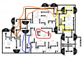
I have my PCB Schematic attached.
red line = alarm trigger point
blue line= manual trigger point
yellow line = 12V+ from battery
orange line = 5V+ from LDO
I will trigger the manual point using a jumper wire by hand. the alarm trigger point and 5V from LDO will go into a alarm clock( mechanical contact)