
I have a circuit for discharging a battery (details below) which is working fine but it needs some additions so that actual current being discharged from the battery can be recorded. Can anyone please help me with this, please?
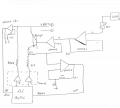
About the circuit : The circuit shown in figure below is being used for discharging a battery (which is connected at the point VBATT on the top right corner.).The battery is drained depending on the value written from the DAC. The value written on the DAC goes through two OPAMPS (A &B) and then to a Darlington transistor which is further connected to a 10 ohm resistor. The resistor is enabled or disabled through a switch. There is another resistor of 680k ohm which can also be used to discharge the battery if DAC is not being used. So, either the value written from the DAC discharges the battery or the 680K.The voltage of the battery (VBATT) is recorded on dsPIC (AD41) and also the emitter voltage of the darlington is recorded (AD42).This system is working as desired. However, I want to record the value of the actual current that is being drained out of the battery. The actual current will be different from the demanded current (Current values written through DAC) when the voltage of the battery is significantly low and it cant provide the current demanded.
Question: How can the actual current be determined from the given circuit? Shall I use a current mirror (or follower), if yes, then how can it be added to this circuit?
Attachments
-
 122.7 KB Views: 17


