 Facebook
 Google
 GitHub
 Linkedin
I have a Pioneer VSX-40 that I am trying to repair. It would not turn on initially. I found the right front channel blown, replaced both transistors and 4 resistors. Now it will power on fine but there is no audio. I am hoping this isn't the DSP fault that happens on other units. I saw a repair video by someone else with a very similar model & fault and he replaced the audio IC. The schematics seem to be for combined models and are found under the VSX-821-K model. I was just wondering if there is a way to test the audio IC & if it needs to be in circuit to be tested? There's isn't much room to access the IC in place. Currently I have the board removed to access the IC.
Attachments
-
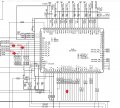 383.8 KB Views: 9


