how to power more led's

Thread Starter

markosillypig

Joined Jul 21, 2008
188
hi all
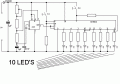
i.m using this led chaser circuit on a project for my garden but i want it to power a bank of 10 led's on each leg of the sequencer so that is 10 led'ssimultaneously 8 outputs for the sequence i asume the led output can be used as a trigger
so what do i have to do to finish the project

thanks
marko
 

Attachments

SgtWookie

Joined Jul 17, 2007
22,230
An easy solution would be to use a ULN2804 Darlington driver IC. It has 8 Darlington drivers with 10.5k base current limiting resistors in it already, just fine for CMOS.

Each channel in the ULN2804 can sink up to around 350mA current continuously. You will lose about 1v across the output.

Digikey stocks ULN2804s:
http://search.digikey.com/scripts/D..._link=hp_go_button&KeyWords=ULN2804&x=22&y=18

You have not mentioned what LEDs you are using, nor their typical Vf @ current specs.
[eta]
If you are using a 9v battery for power, it won't last very long.
 
Last edited:

SgtWookie

Joined Jul 17, 2007
22,230
would a 2n7000 do the job or something a bit bigger ??

or have you got a scamatic for a cmos driver ?
A 2N7000 is a single MOSFET. You would need eight of them, plus eight resistors from the outputs of the 4015 to their gates to keep them from "ringing" when turned on/off.

A ULN2804 is a single 18-pin IC that contains 8 Darlington drivers and base resistors. One part replacing 16 individual parts.

You need to give us some more information:
1) What is the power supply that you are planning on using?
2) What is the typical Vf @ current rating for the LEDs that you are planning on using?
 

SgtWookie

Joined Jul 17, 2007
22,230
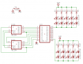
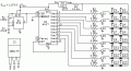
OK, so see the attached. It's basically what you need to do.

Not all of your existing schematic is shown, just some of the 4015 interconnects, and the connections to the ULN2804.

Only two outputs of the ULN2804 are shown; the others need the same kind of connection.

You'll need to supply the LED current limiting resistors right from your 9v supply, not via the 1N4148 diode.

With a 100mA current sink load, the ULN2804 will drop about 0.8v. You say your LEDs are rated for a typical Vf of 3.6v @ 20mA, so two in series is 7.2v
Rlimit >= (Vsupply - (VfLED + VdropDriver)) / 20mA
Rlimit >= (9v - (7.2v + 0.8v) / 0.02 A
Rlimit >= 1/.02 = 50 Ohms. 51 Ohms is the closest standard value.
Rlimit power requirement: 1v x .02 A = 0.02 Watts. Doubled the requirement to 0.04W. You could use any resistor rated for 1/25 Watt or higher.

To keep your parts count low, you could use SIP resistors. Digikey has 6-pin SIPs in stock:
http://search.digikey.com/scripts/DkSearch/dksus.dll?Detail&name=770-61-R51-ND
 

Attachments

Thread Starter

markosillypig

Joined Jul 21, 2008
188
i have had a slight change of mind i'm still looking at the 4015 circuit but what i need to do is to drive a set of 2 led's x8 light chaser actualy all i want now is to make some lights like taxiway lights on a runway
as me and the wife to be love aeroplanes and i want a chaser light set for my garden path to welcome her home after the wedding
thanks all
 

SgtWookie

Joined Jul 17, 2007
22,230
If you want to emulate taxiway lights, you could use the 4015 circuit, but a 4017 Johnson counter would make things easier - and the lights would always strobe in the same sequence.

Cheap super-bright LEDs like you might find on E-bay won't work very well. They have a very narrow focus, and will appear very dim unless you are looking at them within about 25° of their centerline. You would either need to use some kind of conical reflector for each LED, or wide-angle LEDs like a Phillips LumiLED.
 

Wendy

Joined Mar 24, 2008
23,801
I covered that in Chapter 9, Light Chasers in my article, where I mentioned using it for runway lights.

How long do you want the runway to be in terms of LED count?
 
Last edited:

SgtWookie

Joined Jul 17, 2007
22,230
Bill,
He's using a 9v supply. There won't be enough headroom for the LM317.
With an average Vf of 3.4v @ 100mA, that leaves 2.2v. The LM317 needs 3v+ headroom when used in current limiting mode.

The 4017 will be hard-pressed to source enough current to reliably saturate a single BJT with Ic=100mA, as by the book 10mA base current will be required. However, according to ONsemi's datasheet for the PN2222, if base current is >=3mA, Vce should be about 0.1v with Ic=150mA. If the base resistors were reduced to about 2.7k, that could be enough. Of course, this means that PN2222/2N2222 transistors will be required. 2N3904 or 2N4401 would require more base current.

So that leaves about 2.1v to drop. 22 Ohms is a standard value. 1/2 Watt should be a sufficient power rating for the resistor, replacing the LM317.

Marko, you should still use the LM317 circuit to test the Vf of your LEDs. Most of them should fall about midrange (3.4v), but you'll get some that will have higher and lower Vf's. You can use a low Vf LED in series with a higher Vf LED to wind up with the same average voltage drop.
 
Last edited:

Thread Starter

markosillypig

Joined Jul 21, 2008
188
so i'm going to make bill's circuit just one more thing where the hell can you buy a 12.5K OHM resistors from i have looked on ebay farnell and most of the usual places
 
Top