More information on WX-DC12003, and other cheap power modules from AliExpress

Thread Starter

andyenigineerguy

Joined Sep 3, 2017
8
Hi all,

This post is intended to be a revival of this post from >1 year ago asking the same question by @doesntcompute: https://forum.allaboutcircuits.com/threads/looking-for-data-on-wx-dc12003.184237/

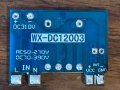
Does anyone have - or know where to get - the schematics, or BOM, or board files for these handy little regulators from Aliexpress? So far, I have tested the 12V 300mA variant (link here)

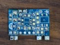
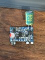
Functionally, it's working very well for me... However I need to explore activating the regulator based on a certain condition (using SHDN pin if available), and also conducting some safety analysis (hence needing to know the BOM). I would really prefer to use these, especially at the price point, but am too conscious of these being sh*tty quality (see attached photo... you get what you pay for I guess )

I've reached out to the AliExpress supplier AGUHAJSU Global purchase Store but have not heard back.

Andy
 

Attachments

Papabravo

Joined Feb 24, 2006
22,058
I think that your best bet is to trace out the PCB and build your own schematic. As far as the BOM that should not be difficult to recreate. It beats waiting for a large Chinese company to consider you worthy of a response.
 

Papabravo

Joined Feb 24, 2006
22,058
I don't think the TS wants to duplicate them as much as he wants to evaluate the design for particular features and analyze the safety of the design. In order to evaluate the transformer, he will have to pull if from the board, measure it, and possibly disassemble it. For those prices he could buy a dozen of them and bin the detritus when he is done.
 

Thread Starter

andyenigineerguy

Joined Sep 3, 2017
8
Thanks for the responses everyone.

@BobTPH that is exactly the point actually! the transformer is more expensive than the whole unit, hence the motivation to try to validate this abnormally cheap design for my purpose.

@Papabravo I agree, creating a schematic would be the logical next step, although I've perhaps answered my own question at this point... The HT2812H does not have an enable/shutdown pin, and the build quality of these guys is unsurprisingly terrible. Transformer soldered at an angle, etc. So
 

Papabravo

Joined Feb 24, 2006
22,058
Thanks for the responses everyone.

@BobTPH that is exactly the point actually! the transformer is more expensive than the whole unit, hence the motivation to try to validate this abnormally cheap design for my purpose.

@Papabravo I agree, creating a schematic would be the logical next step, although I've perhaps answered my own question at this point... The HT2812H does not have an enable/shutdown pin, and the build quality of these guys is unsurprisingly terrible. Transformer soldered at an angle, etc. So
New information always alters the landscape.

Buona fortuna
 
That's cool. Does anyone know what components I need to change in order to change the voltage output? Mine is kind of low, 4.75 (which is technically in spec for the 5V module) but I'd like it a little higher like 5.5 or maybe 6.
 

lehrian

Joined Nov 6, 2024
3
I have been using these cheap noisy power supplies for some time now and recently came across a failure when powering a LoRa radio with them. I found this thread when searching for a schematic for them which I did not find. So I melted one apart and drew a schematic. There are a couple of unknowns as there are two diodes marked F7k which I suspect are Zener diodes but I don't know their breakdown voltage and there is a small MLCC of which I don't know the capacitance (I suspect in the 1uF-10uF range). The current sense resistor, R5, I measured to get the value as it is marked ZR40 which I can't find via search. Attached are my schematic, the bare PCB (both sides) and the PCB w/o the transformer. I also attached an English version of the HT2812H datasheet.
 

Attachments

drjohsmith

Joined Dec 13, 2021
1,559
@andyengeneerguy
you say " conducting some safety analysis (hence needing to know the BOM). "

IMHO, there is no guarantee that the build you get today, is the same as tomorrow's build if you purchase off Alex press et all.
so dont know know what your random sample is going to tel, you
 

lehrian

Joined Nov 6, 2024
3
You are correct, there are at least two different manufacturers of this power supply. The one I have used is marked with WX-DC12003 and they have been very consistent over the 5 years I have been using them. This is the one I disassembled and from which I drew the schematic. There is another manufacturer I have purchased and it is marked with JL-AD3W-HT-V3 and while it seemed to be interchangeable it required additional filtering on the GPIOs of the uP so there is definitely a difference in components when switching to a different manufacturer, as one might expect.
 

ChazLab

Joined Nov 10, 2025
4
I just got 4 of these to test out using in a small standby supply.
I didn't want to have to design my own transformer circuit as that can get very complicated and these looked like such a great cheap alternative ..
It is possibly going to replace an out of production unit i have reverse engineered and modified using two of them for a plus and minus 12 volt supply. i have rudimentary tested out the 12 volt version and so far its pretty good.
You can see them getting slotted in on my board image (not totally finished yet) .
But as some suggested they might be noisy so i am adding additional filtering on the output.. I'm hoping to use this in audio amp circuits but am also concerned with their safety and power ratting. If i can run any tests ill report back..
Thanks lehrian for your contribution..supper helpful.

Start board mage.JPG
 

ChazLab

Joined Nov 10, 2025
4
I have taken some scope readings to try and determine what sort of output filtering would be best effective.
Bottom scope is hard to see but that's at the edge of the transformer (uncoupled) thuss the wave in it and its cut off due to my camera frame rate. but its a decent spiked PWM signal and the top scope is the noise floor on the output..so with a little additional choke and capacitor filter circuit i think i can get away with a nice clean 12 volts
KIMG1357.JPG KIMG1360.JPG
 

drjohsmith

Joined Dec 13, 2021
1,559
the op said they were trying to evaluate safety and implied quality, and how it was built to the cost.

remember

testing a random sample of 1 will not tell you much about quality. the best you can hope for is its terriblele and un usable, so you won't use it,
if its good, or worse ok, you know nothing about the next unit, so again cant trust it to purchase.

, its the "husband dont tell wife I cheated" hypothesis from the tv series house. your response is going to be the same either way.

as for why so cheap,
We had a long chat down pub a few years ago on this .
we discussed
use of counterfeit parts
not paying for development ,
not paying for support / guarantees
not paying for advertising
Chinese "supportive" environment
economies of scale.

in the end , we decided the workers pay to work and live on premises was as good a reason as any we coukd think of.
 
Top